With the Arduino NOT Logic Gate built on the MakerShield, it is time to upload the sketch. Example 5-1 operates the red and green LEDs using a pushbutton switch. Here are the steps you should follow:
- Attach the Arduino to your computer using a USB cable.
- Open the Arduino software and type Example 5-1 into the software’s text editor.
- Upload the sketch to the Arduino.
- Press the mini pushbutton switch for a moment.
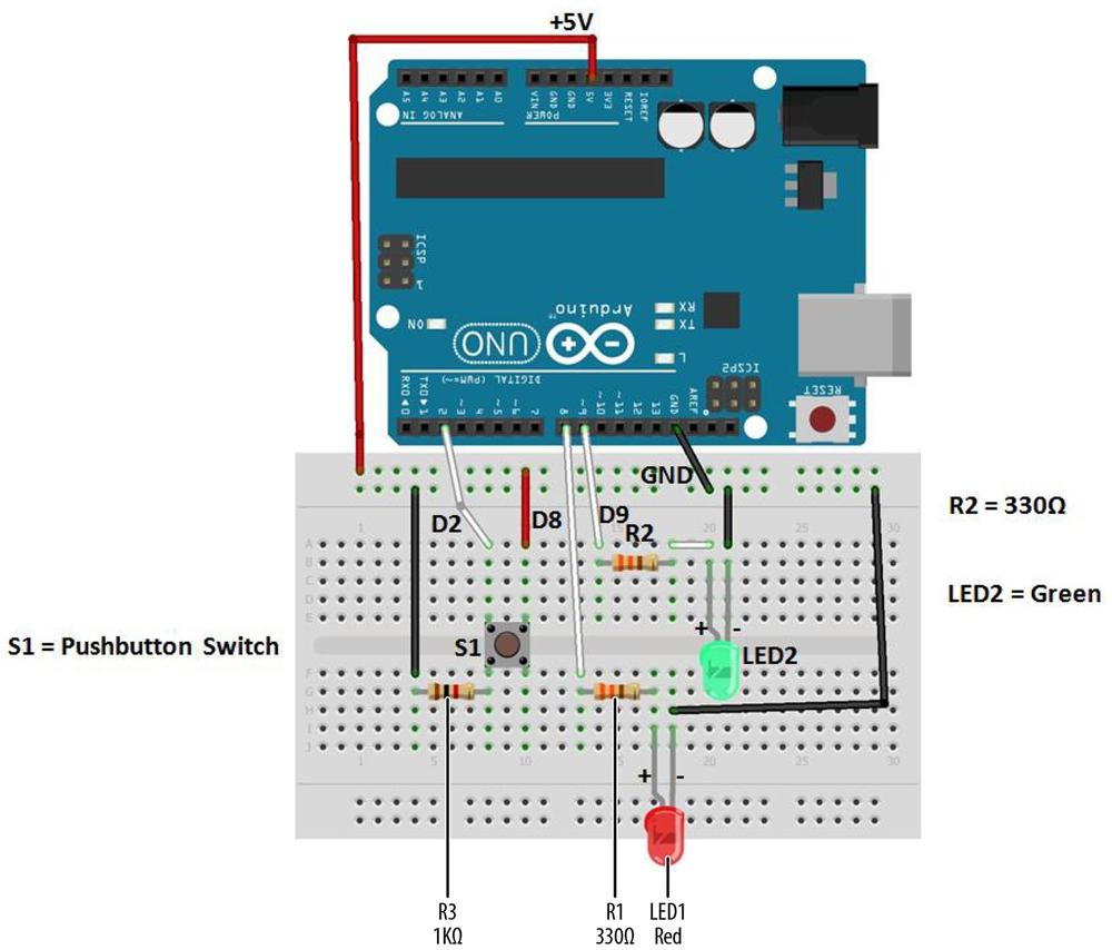
Figure 5-5. The NOT Logic Gate Fritzing wiring diagram
The Arduino NOT Logic Gate will turn the green LED on once the sketch has been uploaded to the microcontroller. Pressing the pushbutton switch will turn the green LED off and the red LED will be on. Figure 5-6 shows the Arduino NOT Logic Gate in operation. The green LED shows a TRUE output state when the pushbutton switch in not pressed. Pressing the pushbutton switch shows a FALSE output state by turning on the red LED. Also,the != in the Arduino sketch is the computer programming symbol for the logical NOT function.
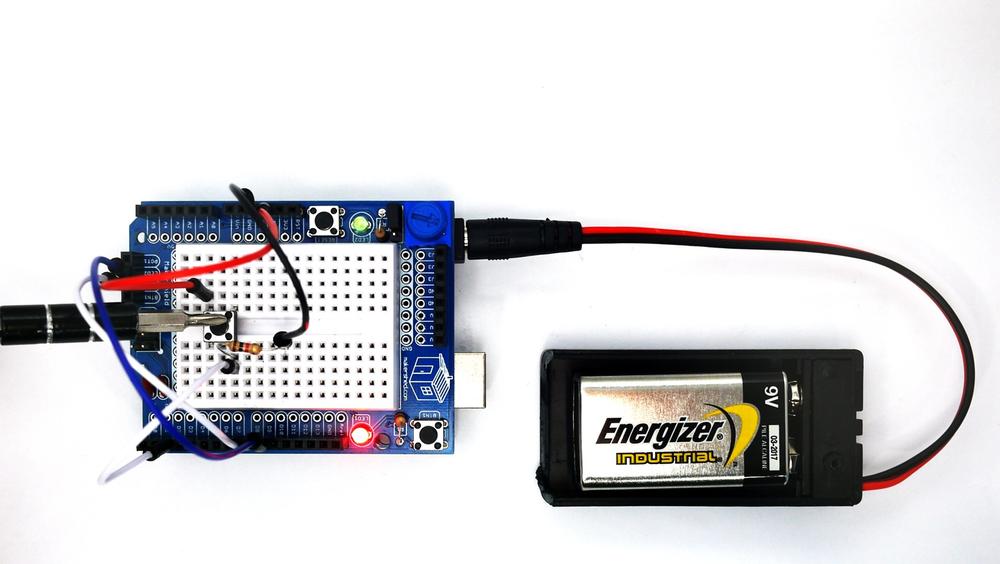
Figure 5-6. The Arduino NOT Logic Gate: pressing the pushbutton switch turns on the red LED (FALSE output)
Example 5-1. The Arduino NOT Logic Gate sketch
/*
  Arduino_NOT_Logic_Gate

  This sketch demonstrates the NOT(Inverter) Logic Gate operation.

  With the pushbutton switch not pressed (Logic LOW input), the green LED
  (Logic HIGH output indicator) is on and the red LED (Logic LOW output
  indicator) is off.
  Pressing the pushbutton turns the green LED off and the red LED on.

 11 September 2013
 by Don Wilcher

 */


// set pin numbers:
int buttonPin = 2;     // the number of the pushbutton pin
int LEDred =  8;      //  pin number for the red LED
int LEDgreen = 9;    //   pin number for the green LED

// variables will change:
int buttonStatus = 0;         // variable for reading the pushbutton status

void setup() {
  // initialize the LED pins as outputs:
  pinMode(LEDred, OUTPUT);
  pinMode(LEDgreen, OUTPUT);
  // initialize the pushbutton pin as an input:
  pinMode(buttonPin, INPUT);
}

void loop(){
  // read the status of the pushbutton value:
  buttonStatus = digitalRead(buttonPin);

  // check if the pushbutton is not pressed
  //
  if (buttonStatus != HIGH) {
    // turn green LED on:
    digitalWrite(LEDgreen, HIGH);
    // turn red LED off:
    digitalWrite(LEDred, LOW);
  }
  else {
    // turn green LED off:
    digitalWrite(LEDgreen, LOW);
   // turn red LED ON:
  digitalWrite(LEDred, HIGH);
  }
}
After the sketch has been successfully uploaded to the Arduino microcontroller, the green LED will be on and the red LED off. Press the pushbutton switch to toggle the on/off states of the LEDs. To test the NOT Logic Gate, use the truth table shown in Figure 5-7.
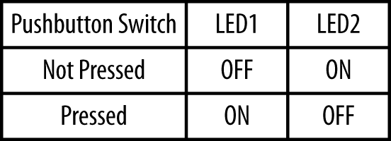
Figure 5-7. The Arduino NOT Logic Gate truth table
TROUBLESHOOTING TIP
If the LEDs do not turn based on the truth table, check your electrical wiring and make sure the LEDs are properly oriented.
The block diagram in Figure 5-8 shows the building blocks and the electrical signal flow for the Arduino NOT Logic Gate. Circuit schematic diagrams are used by electrical engineers to quickly build cool electronic devices. The equivalent circuit schematic diagram for the Arduino AND Logic Gate is shown in Figure 5-9.
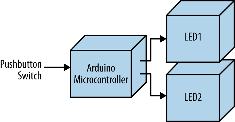
Figure 5-8. The Arduino NOT Logic Gate block diagram
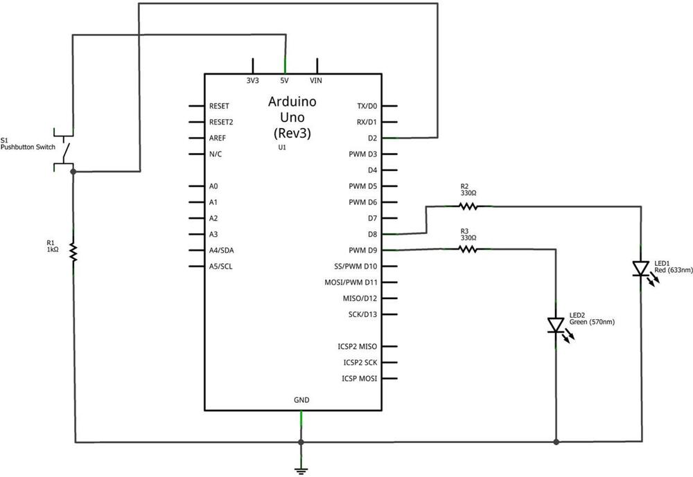
Figure 5-9. The Arduino NOT Logic Gate circuit schematic diagram
Leave a Reply