Gas flow in a reservoir under transient conditions can be approximated by the combination of Darcy’s law (rate equation) and the continuity equation. In general,

which in radial coordinates reduces to

From the real gas law,

and therefore

If the permeability k is considered constant, then Equation (4-64) can be approximated further:

Performing the differentiation on the right-hand side of Equation (4-65) and assuming that Z and μ are either constant or that they change uniformly and slowly with pressure, then

Via rearrangement and remembering that

it becomes

Therefore, Equation (4-65) can be written as

For an ideal gas, cg = 1/p and, as a result, Equation (4-55) leads to

This approximation is in the form of the diffusivity equation [see Equation (2-18) in and its solution, under the assumptions listed in this section, could have the shape of the solutions of the equation for oil, presuming that p2 instead of p is used. developed independently. Pressure squared differences can be used as a reasonable approximation. However, the assumptions used to derive Equation (4-70) are limiting and, in fact, they can lead to large errors in high-rate wells unless using the Al-Hussainy and Ramey (1966) real gas pseudopressure function.
The real gas pseudopressure function, m(p), is defined as

where po is some arbitrary reference pressure (could be zero). The differential pseudopressure Δm(p), defined as m(p) – m(pwf), is then the driving force in the reservoir.
For low pressure it can be shown that

whereas for high pressure (both pi and pwf higher than 3000 psi),

The real gas pseudopressure can be used instead of pressure squared difference in any gas well deliverability relationship (properly adjusted for the viscosity and the gas deviation factor). For example, Equation (4-47) would be of the form

Of course, more appropriately, the real gas pseudopressure can be used as an integrating factor for an exact solution of the diffusivity equation for a gas. Beginning with Equation (4-65), and using the definition of the real gas pseudopressure [Equation (4-71)] and the chain rule, it can be written readily that

Similarly,

Therefore, Equation (4-65) becomes

The solution of Equation (4-77) is exactly similar to the solution for the diffusivity equation in terms of pressure. Dimensionless time has (by convention) been defined as

and dimensionless pressure as

All solutions (such as the line source solution and the wellbore storage and skin effect solution) that have been developed for oil wells using the diffusivity equation in terms of pressure are applicable for a gas well using the real gas pseudopressure. For example, the logarithmic approximation to the exponential integral [compare Equations (2-19) and (2-20)] would lead to an analogous expression for a natural gas. Thus,

This expression can be used for transient IPR curves for a gas well.
Example 4-9. Transient IPR for a Gas Well
With the data for the well in Appendix C, calculate transient IPR curves for 10 days, 3 months, and 1 year.
Solution
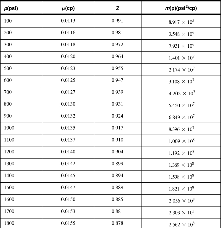
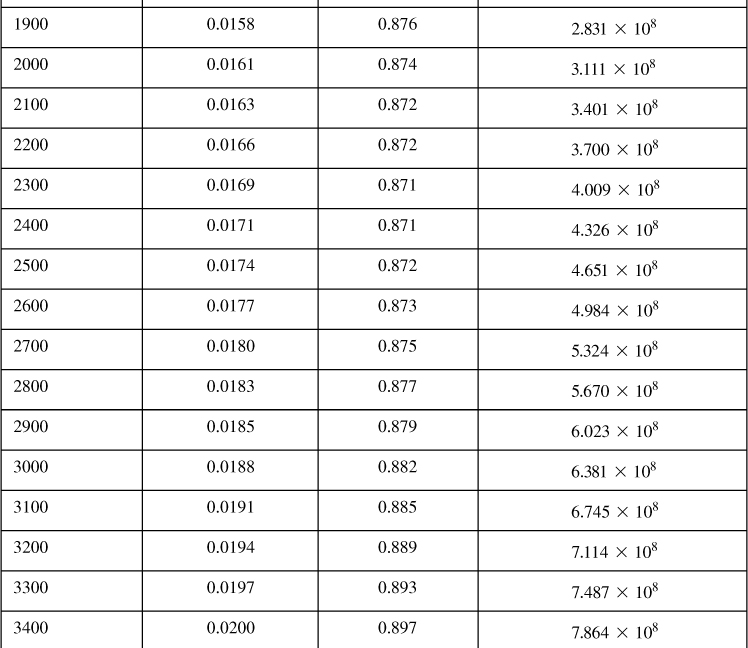
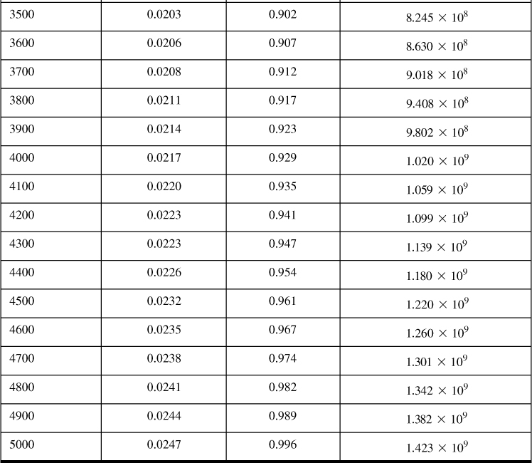
Table 4-6 gives the viscosity, gas deviation factor, and real gas pseudopressure for the reservoir fluid described in Appendix C. For the initial condition of pi = 4613 psi, the real gas pseudopressure, viscosity, and gas compressibility factor are 1.265 × 10⁹ psi2/cp, 0.0235 cp, and 0.968, respectively. (These values, derived from numerical fits, are slightly different from the ones in Appendix C.)
Table 4-6. Calculated Viscosity, Gas Deviation Factor, and Real Gas Pseudopressure for Example 4-9


Equation (4-80) can be used for the transient IPR calculations if real gas pseudopressures are to be used. If pressure squared differences are to be used, then the denominator 1638T must be replaced by 1638μZT.
The gas compressibility can be calculated from Equation (4-35). At initial conditions,

The slope 0.045 was obtained from Figure 4-1 at Tpr = 1.69 and ppr = 6.87. Thus the total system compressibility is

Hence for time equal to 10 days (240 hr), Equation (4-80) becomes

and finally,

Similar expressions can be developed readily for the other times.
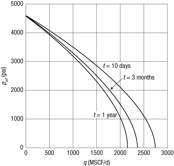
Figure 4-8 is a graph of the transient IPR curves for 10 days, 3 months, and 1 year.

Figure 4-8. Transient IPR curves for Example 4-9.
Note: A large fraction of all natural gas-producing wells are hydraulically fractured, which makes the inflow relationships presented implying radial flow, sometimes invalid. If the reservoir permeability is relatively large (i.e., k > 10 md), then the fracture lengths are relatively short, and the well performance can be described with a fractured well skin factor and a radial flow equation is appropriate. However, in low-permeability reservoirs fracture lengths are very large and radial flow-equivalent skin effects are not appropriate. Fracture-performance models are then indicated. In such cases, non-Darcy flow effects are likely to occur in a hydraulic fracture so these effects need to be included. Reservoir inflow to hydraulically.
Leave a Reply