When I plan to use a device that is new to me, I like to first verify that I understand how it works, before designing the whole system. Because the RTC is new to you, let’s take a look at how it works.
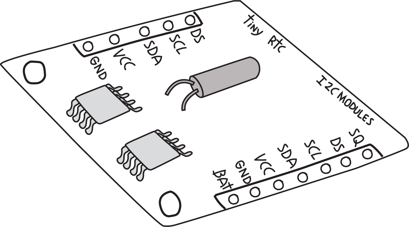
The main part of an RTC is the chip itself. The most common one is the DS1307, which requires a crystal for correct timekeeping and a battery to keep it running when the rest of the system is switched off. Rather than build this ourselves, we’ll use one of the many RTC modules available, saving us time for very little cost.
DS1307 RTC modules are available from many different sources. Fortunately, they all function and interface in very similar ways. I ended up with the TinyRTC, available from Elecrow.

Note that the pins are not always included; you may have to order those separately and solder them in. You can get pins from many sources; for example, Adafruit part #392 includes plenty of pins for this and future projects.
NOTE
If you’re new to soldering, there is a link to a great soldering tutorial in “Soldering Your Project on the Proto Shield”.
This device uses an interface called I2C, sometimes also called the Two Wire Interface (TWI) or simply Wire. Arduino provides a built-in library for the I2C interface (conveniently called Wire), and Adafruit provides a library for the DS1307 called RTClib. To install RTClib, do the following in the Arduino IDE:
- Open the library manager by selecting Sketch->Include Library->Manage Libraries
- In the “Filter your search” box type RTCLib
- Click on the “Install” button for the RTClib by Adafruit
- Click on the “Close” button
You can check that you’ve installed the library correctly by checking the example that comes with this library. You don’t need to build a circuit for this, and technically you don’t even need to have your Arduino handy. In the Arduino IDE, open the File menu and select Examples→RTClib→ds1307 to open an example program. Instead of clicking the Upload button, click the Verify button (see Figure 4-2). If you get the message “Done compiling,” then you have installed the library correctly.
NOTE
After installing a new library, it’s wise to verify that the library is installed properly, and that any libraries it depends on are also installed properly, before you try writing your own program.
Most libraries written for Arduino include examples, and because they were probably written by the same people who wrote the library, they are most likely correct.
The TinyRTC module comes with two sets of pins: one consists of five positions and the other of seven positions. Most of the pins are duplicated, and other pins provide additional features. To test the RTC, you only need to worry about four pins: the two pins that form the I2C interface, power, and ground; the RTC must be provided with 5 V on its pin labeled VCC; and its ground must be connected to the Arduino ground.
NOTE
On the hardware side, I2C is supported by two specific Arduino pins (SDA and SCL), as described in the Arduino Wire Library reference.
For a quick test, you can make use of a common trick: for devices that use very little power, such as the RTC, you can use the digital outputs to provide power by setting one pin to HIGH and another to LOW, if the pins line up properly. An I/O pin that is set to output HIGH is essentially the same as 5 V, and an I/O pin that is set to output LOW is essentially the same as the ground.
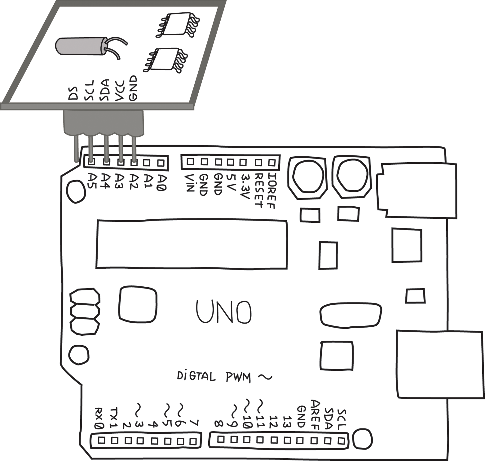
On an Uno, SCL is A5 and SDA is A4. In addition to these two interface pins, we need to connect VCC and GND to any other I/O pins to provide 5V and GND. This can be accomplished by aligning the TinyRTC as shown in Figure 8-3 on the Arduino Uno analogue input pins. You could also use a breadboard and jumper wires to make the connection.

WARNING
Note that on some Arduinos with different microcontrollers, the I2C signals (SDA and SCL) could be on different pins. For this reason, all recent Arduinos with the Uno R3 footprint comply with a new standard pin layout, which adds the 12C pins after AREF. This is in addition to and duplicates whatever other pins happen to be the 12C pins.
Analogue input A4 and A5 will deal with I2C communication, while A2 and A3 will provide power and ground. A3 needs to provide 5 V to the RTC pin labeled VCC, so we will set it HIGH, while A2 will be set LOW to provide ground.
Now we are ready to test! In the Arduino IDE, open the File menu and select Examples→RTClib→ds1307 to open the example program. Before you compile and upload, remember that you need to set up pins A2 and A3 to deliver power to the TinyRTC. Add the following four lines to setup(), right at the very top:
void setup() {
  pinMode(A3, OUTPUT);
  pinMode(A2, OUTPUT);
  digitalWrite(A3, HIGH);
  digitalWrite(A2, LOW);
NOTE
If you are using a board that’s wired differently, you’ll need to use a breadboard and jumper wires to connect it, so you should not add those extra lines of code. Just be sure to wire the board as instructed by the supplier.
While here, note that the example opens the serial port at 57,600 baud.
Now you can upload, and after the upload has completed, open the serial monitor. Check the baud rate selection box in the lower-right corner of the serial monitor, and select “57600 baud”. You should see output resembling this:
2013/10/20 15:6:22
 since midnight 1/1/1970 = 1382281582s = 15998d
 now + 7d + 30s: 2013/10/27 15:6:52

2013/10/20 15:6:25
 since midnight 1/1/1970 = 1382281585s = 15998d
 now + 7d + 30s: 2013/10/27 15:6:55
Note that the date and time may be wrong, but you should see the seconds count increasing. If you get an error, double-check that the RTC is in the right position, i.e., that SCL is connected to A5 etc., and double-check that you set pins A2 and A3 properly in setup().
To set the correct time in the RTC, look in the setup() function. Towards the end you will see this line:
rtc.adjust(DateTime(__DATE__, __TIME__));This line takes the date and time at which the sketch was compiled (__DATE__ and __TIME__, respectively) and uses that to set the RTC. Of course, it might be off by a second or two, but that’s close enough for our purposes.
Copy that line so that it’s outside the if() condition, e.g., just below the rtc.begin():
    rtc.begin();
    rtc.adjust(DateTime(__DATE__, __TIME__));
Compile and upload the sketch, and now the serial monitor should display the correct date and time:
014/5/28 16:12:35
 since midnight 1/1/1970 = 1401293555s = 16218d
 now + 7d + 30s: 2014/6/4 16:13:5
Of course, if your computer has the wrong date and time, this will be reflected here.
After you set the time on the RTC you should comment out the rtc.adjust (and upload the code), otherwise you will keep resetting the time to when that sketch was compiled. This RTC will now keep time for years.
For more information on the library and examples, read Arduino Library and Understanding the Code on Adafruit’s tutorial for theirDS1307 Breakout Board kit.
Note that while the Adafruit board is different, the code is the same.
Now that you feel comfortable with the RTC, let’s move on to the relays.
Leave a Reply