Figure 12.13 shows stress and strain produced in a compound rod.


Figure 12.13 An Assembly of Tube and Bolt
where r subscript is used for rod. Rod is subjected to tensile stress and tube is subjected to compressive stress.
The reduction in length of tube and extension in rod may be different due to difference in materials of tube and rod.
Example 12.7: A steel rod of 20 mm diameter passes centrally through a steel tube of internal and external diameters of 25 and 30 mm, respectively. The tube is 800 mm long and is closed by rigid washers of negligible thickness which is fastened by nuts threaded on the rod. The figure of the assembly is shown in Figure 12.14.
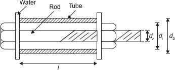
Figure 12.14 Compound Bar as an Assembly of Tube and Rod
dr − Diameters of steel rod = 20 mm
di − Internal diameters of tube = 25 mm
d0 − External diameters of tube = 30 mm
l − Length of tube = 800 mm
- The nuts are tightened until the compressive load on the tube reaches 25 kN, calculate the stress on the tube and the rod.
- Find the increase in these stresses when one nut is tightened by one quarter of a turn relative to the other. There are five threads per 10 mm. Take E = 200 kN/mm2.
Solution:
When nut is tightened, there will be compressive load on the tube which will be equal to the tensile load on the rod. Compressive stress cannot be equal to tensile stress because it depends on cross-section area and strength of the material.
| Pr = Pt = P, | where Pr and Pt are loads on rod and tube, respectively. |
| σrAr = σtAt, | where σr and σt are tensile stress on rod and compressive stress on tube, respectively; and Ar and At are the cross-sectional areas of the rod and tube, respectively. |

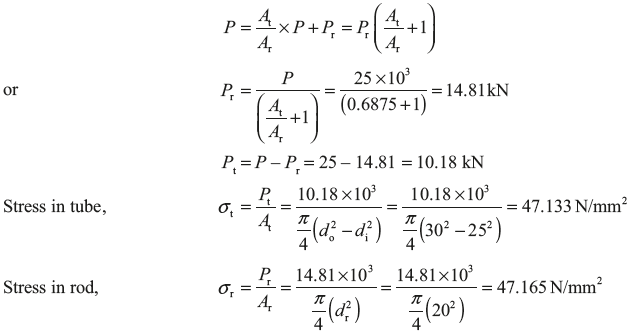
- Compressive stress on tube,
 Tensile stress on rod, σr = 0.6875 σt = 0.6875 × 115.74 N/m2 = 79.57 N/mm2
 - Let
 and
and  be the stress due to tightening of nut by one quarter of a turn.
  But, contraction in the tube + Extension in the rod = Axial movement of the nut
Example 12.8: In Example 12.7, nut is removed and tube and rod are welded to washers and compressive load of 25 kN is applied on washers as shown in figure given below:
Find the stresses in tube and rod.
Solution:
In this case change in length in tube and rod will be same as shown in Figure 12.15.
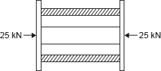
Figure 12.15 Fixed End of Tube and Rod Assembly

On solving Eqs (12.3) and (12.4), we get
Example 12.9: A solid steel bar 0.5 m long and 0.07 m in diameter is placed inside an aluminium tube having 0.075 m inside diameter and 0.10 m outside diameter. The steel bar is 0.15 mm longer than the aluminium tube as shown in Figure 12.16. An axial load of 600 MN is applied to the bar and cylinder through rigid cover plate as shown in figure given below:
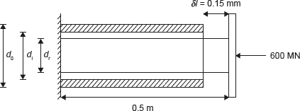
Figure 12.16 Steel Bar and Aluminum Tube Assembly
Find the stress developed in steel bar and cylinder through rigid cover plate.

Let compression in tube is δlA1 m.
Therefore, the compression in steel bar, δlsteel = δlA1 + (0.15 × 10⁻³) m.
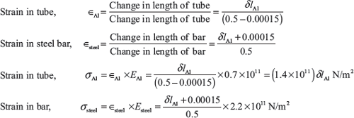
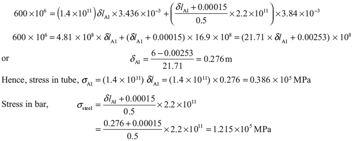
Total load on assembly = Load on tube + Load on steel bar = σA1 × AA1 + σsteel × Asteel
Example 12.10: A concrete column of 37.5 cm2 cross-section, reinforced with steel rods having a total cross-sectional area 7.5 cm2 carries a load of 800 kN as shown in Figure 12.17.
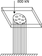
Figure 12.17 Concrete Column
If E for steel is 15 times greater than that of concrete, calculate the stresses produced in steel, and concrete.
Solution:

Contraction in both the steel and concrete will be same.


From Eq. (12.5)

Leave a Reply