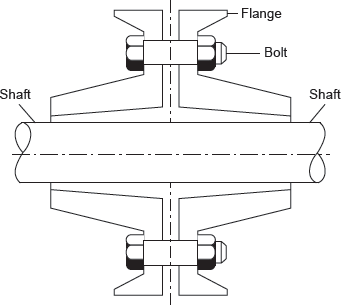
Rigid couplings are designed to draw two shafts together tightly so that no relative motion can occur between them. This design is used for some special kinds of equipment in which precise alignment of two shafts is required. In such cases, the coupling must be capable of transmitting the torque in the shafts. Rigid couplings should be used only when the alignment of the two shafts can be maintained very accurately, not only at the time of installation but also during operation. If significant angular, radial, or axial misalignment occurs, stresses that are difficult to predict and that may lead to early failure due to fatigue will be induced in the shafts. The load path is from the driving shaft to its flange, through the bolts, into the mating flange, and out to the driven shaft. The torque places the bolts in shear.
It consists of two cast iron flanges which are keyed to the shafts to be joined as shown in Figure 16.1. The flanges are brought together and are bolted in the annular space between the hub and the protecting flange. The protective flange is provided to guard the projecting bolt heads and nuts. The bolts are placed equispaced on a bolt circle diameter and the number of bolt depends on the shaft diameter d.

Figure 16.1 Rigid Flange Coupling
Advantages of rigid flange coupling
- It has high torque transmission capacity.
- It is easy to assemble and disassemble.
- It has simple design and is easy to manufacture.
Disadvantages of rigid flange coupling
- It cannot tolerate misalignment between two shafts.
- It can be used only where the motion is free from shocks and vibrations.
- It requires more space than that of other coupling like muff coupling.
Leave a Reply