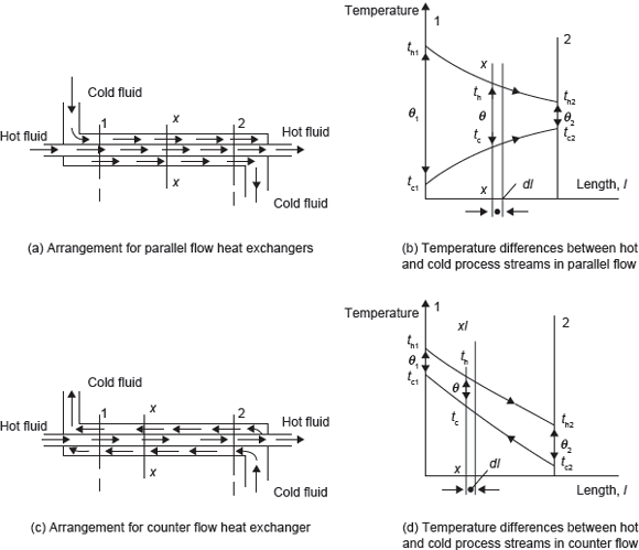
Consider the case of a fluid flowing through a pipe and exchanging heat with a second fluid flowing through an annulus surrounding the pipe. When the fluids flow in the same direction along the pipe the system is known as parallel flow, and when the fluids flow in opposite directions to each other the system is known as counter flow. Parallel flow is shown in Figure 7.9a, b; and counter flow heat exchanger is shown in Figure 7.9c, d.

Figure 7.9 Parallel and Counter Flow Heat Exchangers
Let the mean inlet and outlet temperatures of hot fluid be th1 and th2, respectively, and let the mean temperature of cold fluid at sections 1 and 2 be tc1 and tc2, respectively. Let the mass flow rates of hot fluid and cold fluid be m· h and m· c, respectively. The temperature difference at section 1 is (th1 – tc1) = θ1, and temperature difference at section 2 is (th2 – tc2) = θ2.
There is tubular arrangement for parallel and counter flow heat exchangers. Therefore, the electrical analogy for heat transfer from one fluid to another can be given as

where ho, hi are the heat transfer coefficients for the fluid flow outside the inner tube and inside the inner tube, respectively. ro and ri are the outer and inner radii of inner tube and Ao and Ai are the outer and inner surface area of inner tube.
If we define overall the heat transfer coefficient, U as

Consider a section X–X, where hot fluid is at th and cold fluid is at tc. The temperature difference at this section is (th – tc) = θ, and a small amount of heat, dQ, is transferred across an element of length dl. Now using the equation, Q = U × A × (th – tc)
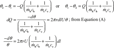
dQ = 2π rdlθ (7.1)
where r is mean radius of the tube.
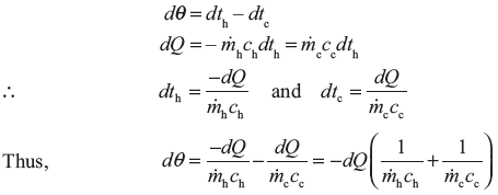
In the case of parallel flow heat exchanger, temperature th decreases with the length l, while temperature tc increases with the length l. The heat given up by hot fluid must be equal to heat received by cold fluid for parallel flow.

On integrating, we get

Also, on integrating, we get

In the case of counter flow, both temperatures th and tc decrease in the direction of the length l.
Therefore, 
Similar to the parallel flow, for counter flow we can find 
 is known as logarithmic mean temperature difference (LMTD).
Thus,
Q = UAθm
where
A = 2πrl
Example 7.7: Exhaust gases flowing through a tabular heat exchanger at the rate of 0.25 kg/s are cooled from 360°C to 100°C by water initially at 15°C. The specific heat of exhaust gases and water may be taken as 1.14 and 4.18 kJ/kgK, respectively; the overall heat transfer coefficient from gases to water is 140 W/m2K. Calculate the surface area required when the cooling water is 0.5 kg/s for parallel flow and counter flow.
Solution:
- For parallel flow as shown in Figure 7.10Heat given up by exhaust gas is equal to heat taken up by water. Therefore,
 Figure 7.10 Parallel Flow Heat Exchanger
- For counter flow as shown in Figure 7.11Heat given up by exhaust gas is equal to heat taken up by water. Therefore,
 Figure 7.11 Counter Flow Heat Exchanger
Leave a Reply