In the T–s diagram (Figure 5.22),
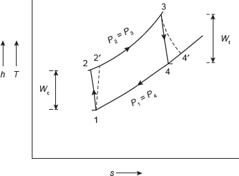
Figure 5.22 Actual Brayton Cycle
For maximum work done, Wnet should be differentiated with respect to c and equating to zero.
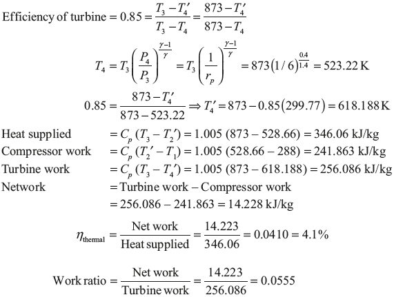
Example 5.5: In a gas turbine plant, air is compressed from 1 bar and 15°C through a pressure ratio 6:1. It is then heated to 600°C in a combustion chamber and expanded back to atmospheric pressure of 1 bar in a turbine. Calculate the cycle efficiency and the work ratio. The isentropic efficiency of the turbine and compressor are 85% and 80%, respectively.
Solution:
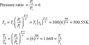
T–s diagram for the gas turbine is shown in Figure 5.23.
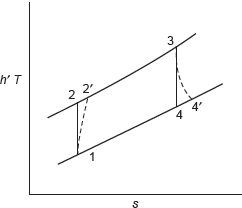
Figure 5.23 T–s Diagram
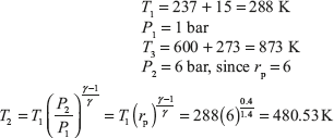
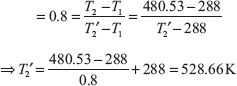
Efficiency of compressor
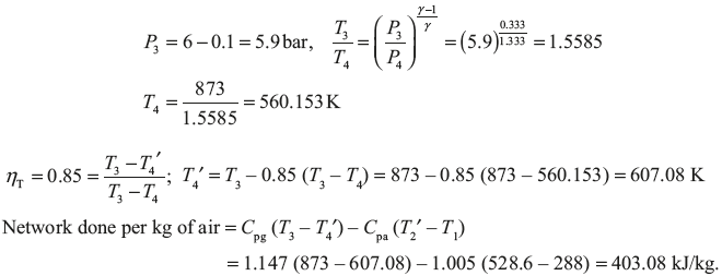
Example 5.6: In Example5.5, if the combustion efficiency is 0.98, fall in pressure through combustion chamber is 0.1 bar. Determine
- The thermal efficiency.
- The work ratio.
- Air rate in kg/kW.
- The specific fuel consumption.
- The air–fuel ratio. For air Cp = 1.005 kJ/kg K; ṁ = 1.333. Calorific value = 42,700 kJ/kg.
Solution:
From solution of Example 5, T1 = 288 K, T2 = 480.53 K, T2′ = 528.6 K, T3 = 873 K


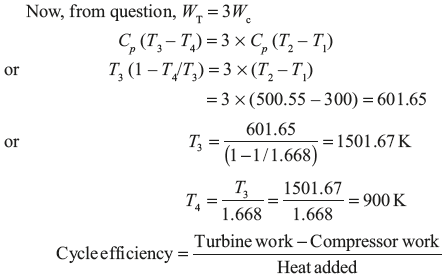
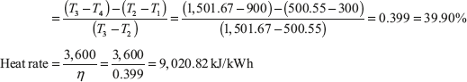
Example 5.7: Air enters the compressor of gas turbine plant operating on Brayton cycle at 1 bar and 27°C. The pressure ratio in the cycle is 6. Calculate the maximum temperature in the cycle and the cycle efficiency, heat rate. Assume WT = 3Wc where WT and Wc are the turbine and compressor work, respectively. Take ṁ = 1.4.
Solution:
T–s diagram for the gas turbine is shown in Figure 5.24.
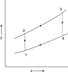
Figure 5.24 T–s Diagram
Leave a Reply