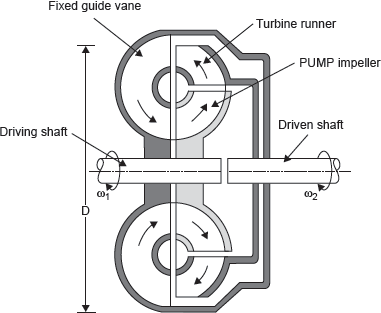
In this case, torque on the driver and driven shafts are equal. The application is for direct drives of machines. But in some cases, the torque required at the driven shaft could be more than the torque on the driver shaft. In this case, speed will be in the reverse ratio. Such an application is in automobiles where this is achieved in steps by varying the gear ratios. The desirable characteristics are a stepless variation of torque. The torque converter is thus superior to the gear train having few gear ratios. A sectional view of torque converter is shown in Figure 9.31.

Figure 9.31 Hydraulic Torque Converter
It consists of three elements, namely, pump impeller, runners, and a fixed guide vane. The pump is connected to the driver shaft. The guide vanes are fixed. The runners are connected to the driven shaft. All the three are enclosed in a casing filled with oil. The oil passing through the pump impeller receives energy and passes to the runners where energy is extracted from the oil to rotate the shaft. Then the oil passes to the stationary guide vanes where the direction of oil flow is changed. This introduces a reactive torque on the pump which increases the torque to be transmitted. The shape, size, and direction of the guide vanes control the torque. Speed ratio will be the inverse of torque ratio. The efficiency is found to be highest at speed ratio of about 0.6.
Leave a Reply