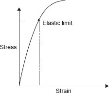
Hooke’s law states that stress and strain are proportional to each other under elastic limit. Originally, Hooke’s law specified that stress was proportional to strain but later Thomas Young introduced constant of proportionality which is known as Young’s modulus of elastic. Further, this name was superseded by modulus of elasticity. Figure 12.3 demonstrates the Hooke’s Law.

Figure 12.3 Hook’s Law

where E is modulus of elasticity, σ is stress, and ∈ is strain.
Working Stress, Allowable Stress, and Factor of Safety:
Working stress is defined as the actual stress of a material under a given loading. The maximum safe stress that a material can carry is termed as the allowable stress. The allowable stress should be limited to values not exceeding the proportional limit. However, since proportional limit is difficult to determine accurately, the allowable stress is taken as either the yield point or ultimate strength divided by a factor of safety. The ratio of this strength (ultimate or yield strength) to allowable strength is called the factor of safety.
The relationship between gauge length and cross-sectional area of the tensile test specimen can be given as ![]() , where A is area of cross-section.
, where A is area of cross-section.
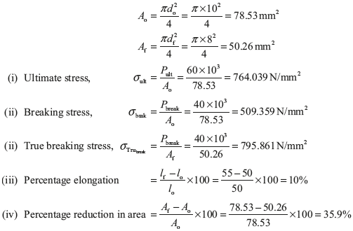
Example 12.1: A mild steel specimen with an original diameter of 10 mm and gauge length of 50 mm was found to have an ultimate load of 60 kN and breaking load of 40 kN. The gauge length at rupture was 55 mm and diameter at rupture cross-section was 8 mm. Determine (i) the ultimate stress, (ii) breaking stress, (iii) true breaking stress, (iv) percentage elongation, and (v) percentage reduction in area.
Solution:
Given: lg = 50 mm, do = 10 mm, lf = 55 mm, Pult = 60 kN, Pbreak = 40 kN, and df = 8 mm.

Stress and Strain in Simple Stepped Bar
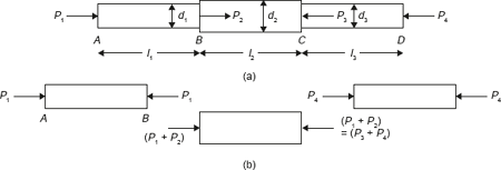
Let us consider a stepped bar of diameters d1, d2, and d3 as shown in Figure 12.4 (a). Different forces of magnitude of P1, P2, P3, and P4 are acting at different sections of the bar. Free body diagram of these sections is shown in Figure 12.4 (b).

Figure 12.4 StressStrain in Stepped Bar


Here δ is total deflection in the bar.
Example 12.2: There is a specimen for tensile test of a material. It has a circular cross-section and enlarged ends as shown in figure given 12.5.

Figure 12.5 Specimen for Tensile Test
The total elongation is 10 mm. The lengths of the enlarged ends are equal to 50 mm and diameter 25 mm for each end. The length and diameter for the middle portion is to be found. The tensile loads applied at the ends are 90 kN and stress produced in the middle potion is 450 MN/m2. Find the length l and diameter d for the middle portion of the specimen. E = 2 × 10⁵ MPa.
Solution:
Cross-section area of the middle portion ![]()
Stress produced in the middle portion 

Elongation produced in the end portions of the specimen

Example 12.3: A brass rod in static equilibrium is subjected to axial load as shown in Figure 12.6.

Figure 12.6 A Bar Under Static Equilibrium
Find the load P and change in length of the rod if its diameter is 100 mm. Take E = 80 GN/m2.
Solution:
Draw the free body diagram for each part of the rod as shown in Figure 12.7.

Figure 12.7 Free Body Diagram

Leave a Reply