Corrosion testing of metals
One of the most damaging environmental effects of aerospace metals is corrosion. Corrosion of the metal alloys used in aircraft structures and engines occurs in many forms, including general corrosion, stress corrosion, pitting corrosion, crevice corrosion and exfoliation corrosion. The describes the corrosion properties of metals. There is no single, universal corrosion test; instead there are a large number of tests used to measure the resistance of metals to different types of corrosion. The tests are often performed under extreme corrosion conditions to accelerate the corrosion rate and thereby determine the long-term corrosion performance of metals.
Most tests have been designed to measure (either quantitatively or qualitatively) the resistance of metals to a specific type of corrosion or corrosive environment. For example, tests are available to determine the resistance of metals to pitting corrosion whereas other tests are used to measure the resistance of metals to crevice corrosion. Aerospace companies may sometimes use their own corrosion test methods, such as exposing structural metals to aviation fuels, lubricants or paint strippers that may contain potentially corrosive chemicals. Jet engine manufacturers perform specialist corrosion tests of the materials used in turbine blades and discs that involve hot combustion gases produced by aviation fuel.
The selection of corrosion tests for metals used in aircraft should be based on the types of corrosion and corrosive environments most likely to be experienced in service. An example of a test used to measure the corrosion rate of aircraft metals is the salt spray test. This test involves exposing metal specimens to a dense saline fog within a closed chamber. The fog is produced by producing a fine mist of salted solution (usually water containing sodium chloride to replicate seawater). The appearance of corrosion products and damage on the specimen is evaluated after a period of time. Mechanical tests can be performed on the specimen after testing to determine whether the corrosion affected the strength and fatigue properties.
Environmental testing of composites
The greatest environmental problem with fibre–polymer composite materials used in aircraft structures is moisture absorption. Water moisture in the atmosphere (humidity) is absorbed into the polymer matrix causing swelling, damage and softening of the material under extreme conditions. Moisture absorption can also reduce the maximum operating temperature of a composite, sometimes by 20 °C or more. Composites typically absorb anywhere from 0.5 to 2% of their own weight in water, and this resides as water molecules in the polymer matrix and along the fibre–polymer interface. The moisture content is often higher in sandwich composites because the water can condense in the core material. Composites can also absorb other types of fluids, including aviation fuel, although airborne water is the biggest problem.
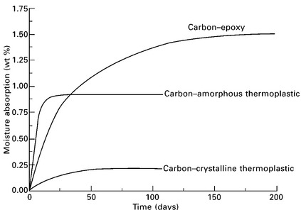
Material specimens are tested under conditions representative of extreme cases of environment: cold temperature and dry; room temperature and dry; hot and dry; and hot and wet. Of these conditions, the worse case for polymer composites is hot and wet representative of a tropical environment. Specimens are placed inside a sealed chamber which simulates a severe tropical environment with a temperature of 71 °C (160 °F) and high humidity (85–95% water). At regular intervals the specimens are removed from the chamber to be weighed. The change in specimen weight indicates the amount of moisture absorbed by the composite. Figure 5.25 shows the weight gain for several types of carbon-fibre composite materials during exposure to hot–wet conditions. The mechanical properties of the specimens are measured at increasing intervals of exposure time, particularly the matrix-dominated properties such as compression strength. This data is used to assess likely changes to the mechanical behaviour of structural composites over the life of an aircraft. Other environmental tests may also be performed on composites, including exposure to ultraviolet radiation.

5.25 Moisture uptake–time curves for several aerospace composite materials. adapted from F. C. Campbell, Manufacturing Fig. technology for aerospace structural materials, Elsevier, 2006
Leave a Reply