Most electronic circuits are completely defined by two things: 1) which components are used and 2) how they are to be connected. By capturing only this information as clearly as possible, a schematic diagram is the clearest way to visualise and communicate an electronic circuit.
A schematic diagram intentionally does not convey the size, shape, or colour of components, or how they are physically placed next to each other, because this information is not relevant to the definition of the circuit; rather, these are construction details for a particular implementation of that circuit.
Each component is represented by a schematic symbol, which unambiguously identifies the component, but says nothing about its size, colour, etc.
In some cases, schematic symbols look very much like the components they represent, while in other cases they are quite different. In particular, you will see that the schematic symbol for an Arduino does not look at all like an Arduino. From the point of view of a schematic diagram, the only thing that matters about an Arduino is that it has certain pins (power, inputs, outputs, etc.). Thus, it is drawn as a very plain box with just the pins indicated.
Electronic schematic symbols and diagrams are designed to convey their functions as quickly and clearly as possible, and some conventions have become common. Two of the most important conventions are as follows:
- The lowest voltage is shown at the bottom of the schematic diagram, and the highest voltage is at the top. Usually this means that the GND connection is at the bottom and that 5V (or a higher voltage if that’s used) is at the top.
- The information flows from left to right. Thus sensors and other input devices are shown on the left, and outputs such as motors, LEDs, relays, and water valves are on the right. If the information travels from Arduino to the MOSFET to a relay to a water valve, they will be shown on a schematic diagram in that order from left to right, even though when you build your circuit, you will have different priorities and your layout may be quite different.
The schematic symbol for an Arduino reflects these conventions too: VIN, 5V, and 3V3 are at the top, GND is at the bottom, and the various controls (RESET, AREF, etc.) are on the left because they are inputs to the Arduino. Although Arduino has three GND pins, only one is shown on the schematic symbol since they are electrically identical. Because the digital and analogue pins can be either inputs or outputs, their placement is somewhat arbitrary.
You can learn more about schematic diagrams in Appendix D.
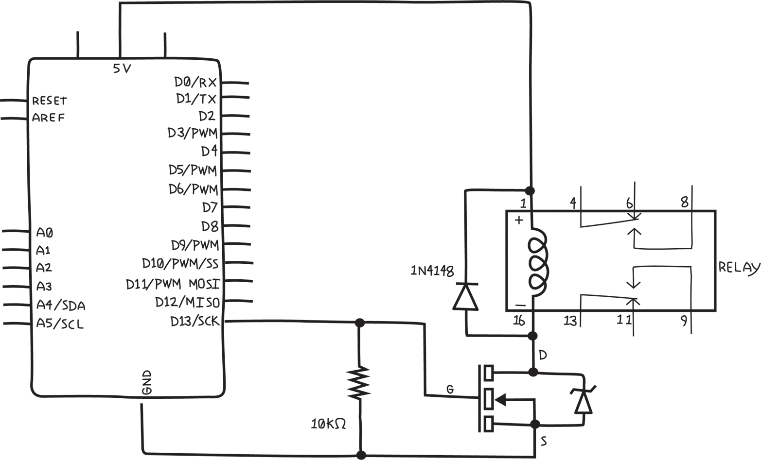
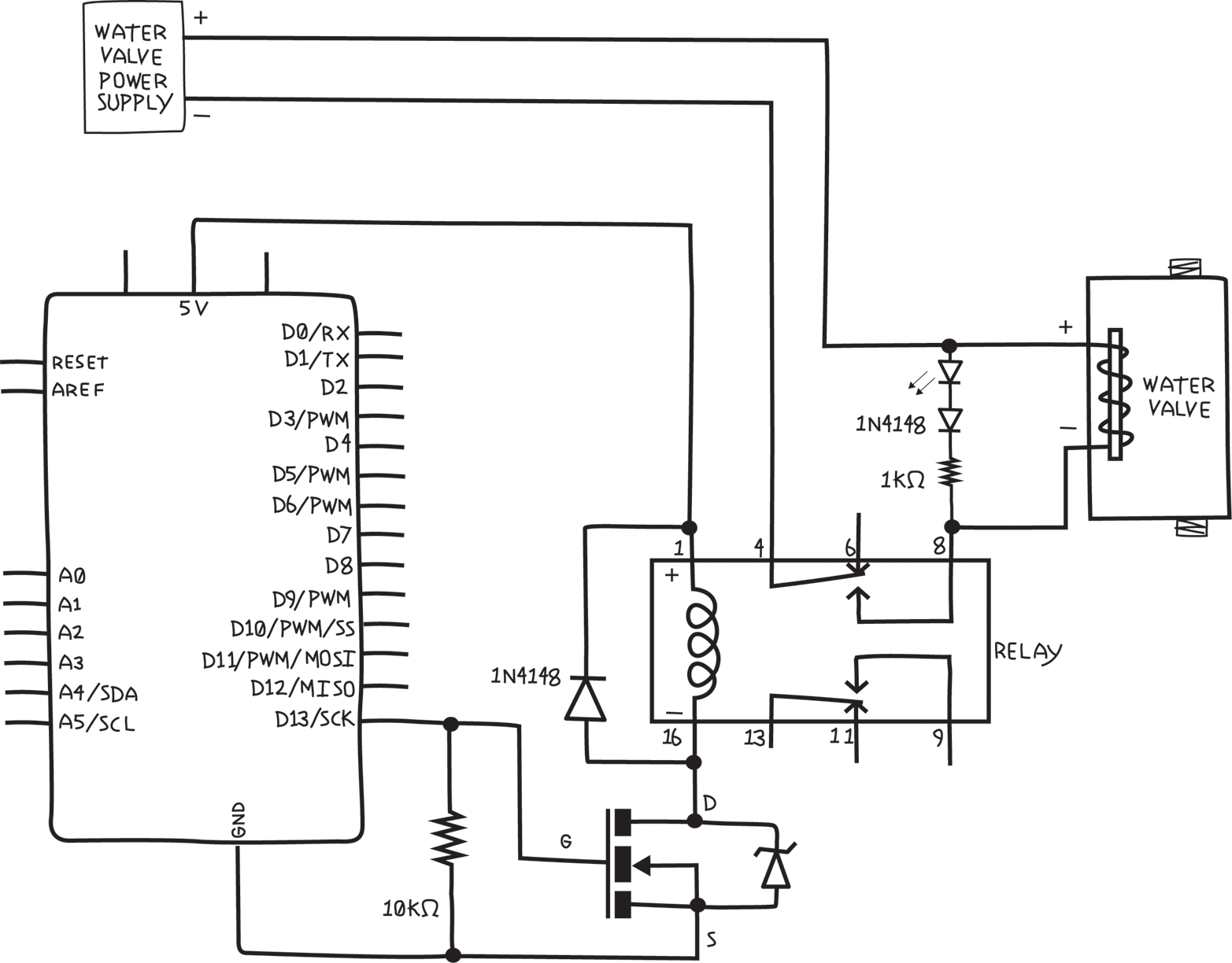
Back to the project at hand: Figure 8-5 shows the schematic diagram for the circuit we’ve been discussing. Remember, the goal is to verify that we can control a relay by using a MOSFET (although the finished system will have three water valves, for the purpose of verifying that the plan works, we need to check only one).
WARNING
Note the pin numbers next to the schematic symbol of the relay. These are important because they tell you which pin is connected to what inside. It is critical to understand this in order to wire up your circuit properly. Note that the pin spacing is not equal: pins 1 and 4 are farther apart than pins 4 and 8. Note that there is a black stripe on the top between pins 8 and 9. Finally, note that the pin numbers are as viewed from the bottom.
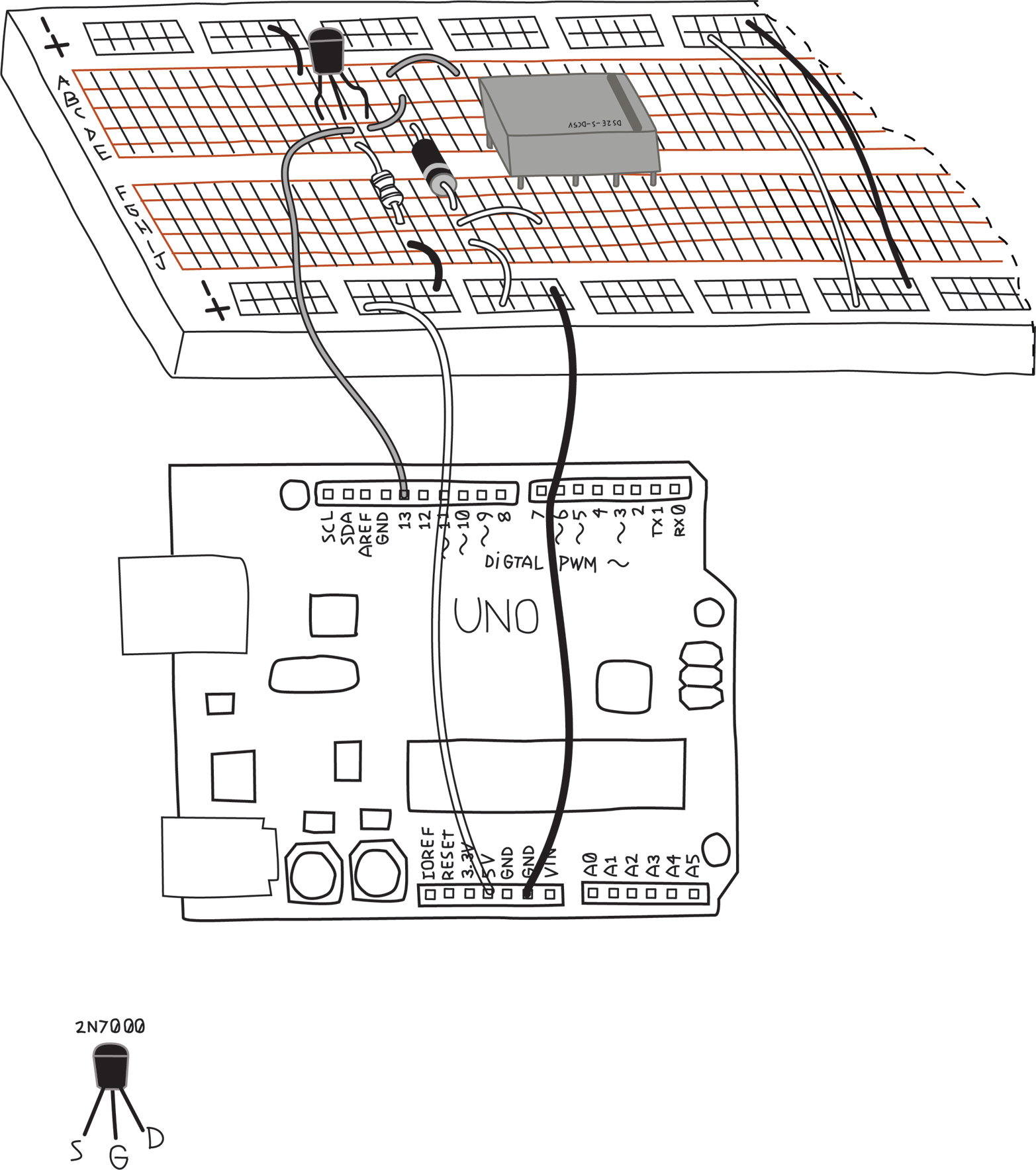
For reference, Figure 8-6 is a picture of the same circuit on a solderless breadboard in the style we’ve used up to now. You might think of this as a pictorial circuit diagram, as opposed to the schematic in Figure 8-5.
WARNING
Just like the relay, the MOSFET pins must be properly identified and wired up correctly. Note that the MOSFET has a curved side and a flat side, as shown in Figure 8-6. This is necessary to indicate the proper order of the pins. Be aware that this order is particular to the 2N7000, but is not necessarily universal. Other MOSFETs might have a different order of the pins. You always have to check the data sheet to find the order of pins for your particular MOSFET.
Pay attention to the diodes, MOSFET, and the relay: the diodes are polarized, the MOSFET must have the flat side facing the right way, and the relay needs to have the stripe at the proper end for everything to work.
If you look at Figure 8-5 and Appendix D, you’ll notice that some components, like resistors, light sensors, and (some) capacitors, have circuit symbols that are symmetrical, in that you can flip them upside down and they look exactly the same, while other components, like LEDs, diodes, and MOSFETs, are not symmetrical. Resistors, light sensors, and (some) capacitors are unpolarized, meaning they work the same regardless of which way the current flows through them, while components, like LEDs and diodes, are polarized, meaning they work differently depending on which way the current flows through them. Similarly, MOSFET pins have very specific functions, and can’t be used interchangeably. While not uniformly true, generally components that have symmetrical schematic symbols are unpolarized, and components with asymmetrical schematic symbols are polarized.
Once you’ve built the circuit, the next step is to write the sketch. For testing, I prefer to use one of Arduino’s built-in examples, if possible, since I know the sketch is correct. Because the relay will make a faint clicking sound when activated, if you run the Blink example, you should hear the relay clicking once a second, and you won’t have to write a line of code.
Before uploading the sketch, verify that the sketch is controlling the pin that is attached to the MOSFET. If you have followed the schematic, you will be connected to pin 13, which is in fact the pin that is controlled in the Blink example sketch. Additionally, the LED will blink at the same time the relay should click.
WARNING
Before you upload a sketch, it’s a good habit to verify that the pins used in the sketch are indeed the pins that you have wired up. You might have a perfectly correct sketch, and a perfectly built circuit, but if your sketch uses different pins than your circuit, things won’t work, and you might waste lots of time trying to find the problem.
If you don’t hear the relay clicking, check the troubleshooting. Remember, the clicking is very faint; you’ll need to put your ear very close to the relay and be in a very quiet room.
Now we can add the water valve. The water valve will connect to the relay and its own power supply. The water valve and power supply probably come with stranded wire, which is almost impossible to use with a solderless breadboard. You’ll find it handy to attach a short piece of solid-core wire to the stranded wire when you’re working with a solderless breadboard, as shown in Figure 8-7.

You’ll need to insulate the joint with some electrical tape or heat shrink tubing to prevent it from touching a wire that it shouldn’t.
WARNING
Whenever you have an exposed piece of metal, such as the wires you just joined together, or the long, bare leads of a photoresistor, or even something that is not part of the circuit, like a screw, you need to make sure that it can’t touch other parts of a circuit, making a connection that you don’t want. This is called a short circuit, and it can make your project fail to work properly. To prevent short circuits, always insulate any exposed wires or secure things in such a way that they can’t move and touch something that they shouldn’t.
You are probably already familiar with electrician’s or insulating tape, which is a common, inexpensive, and easy method. A more professional technique is to use heat shrink tubing. The tubing is cut to size and slipped over the exposed wires or connections, and then heated up with a heat gun, which causes the tubing to shrink tightly around the connection.
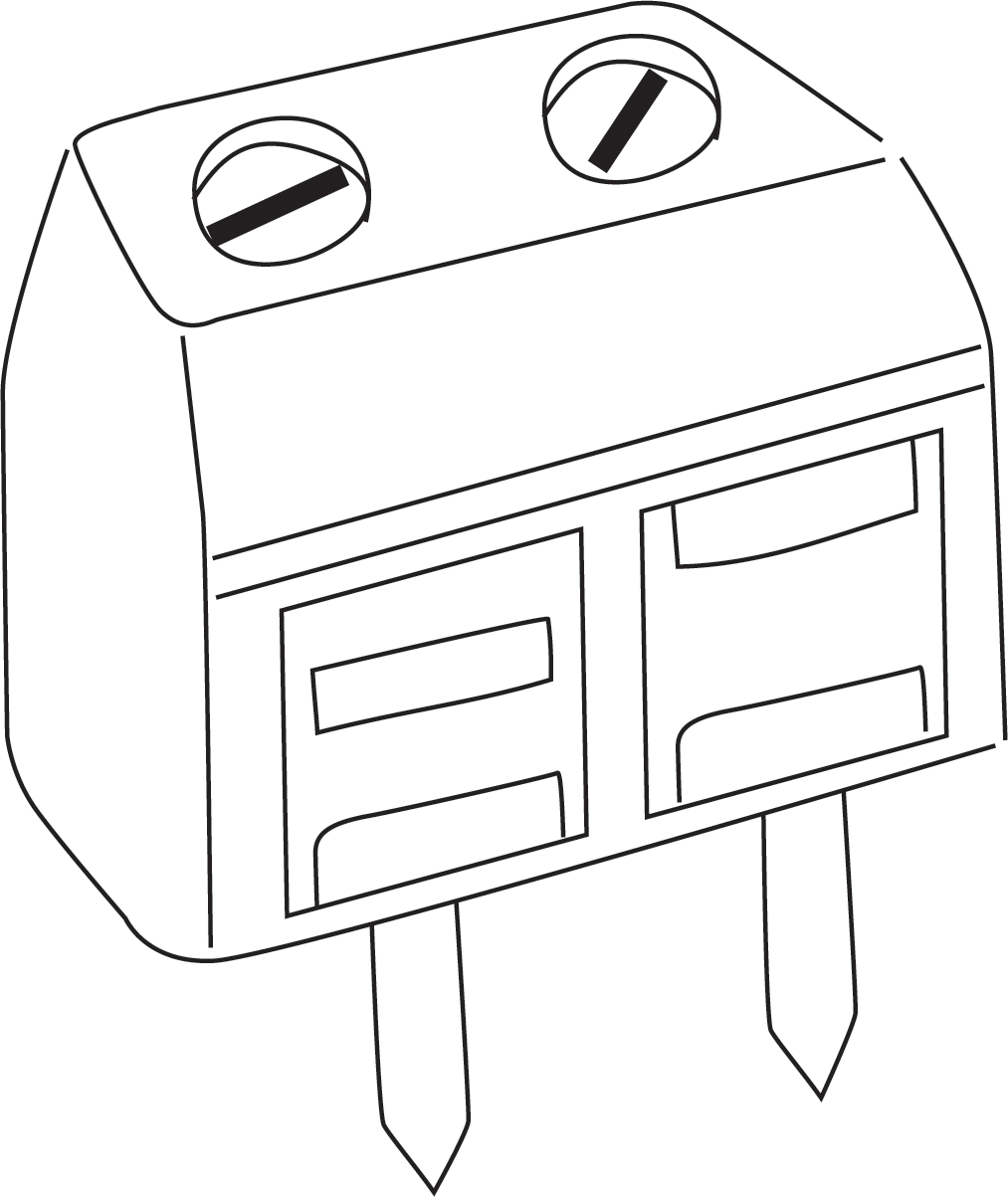
At this point you might realise that you’ll need a way to make this connection when you build the final system. There are many ways to do this, but good-quality screw terminals are a great choice, as shown in Figure 8-8.
So you have another addition to your shopping list. Here are the additions to take us to revision 0.2 of the shopping list:
- Four two-position screw terminals (one pair for each water valve, plus one pair for the water valve power supply) e.g., Jameco part no. 1299761
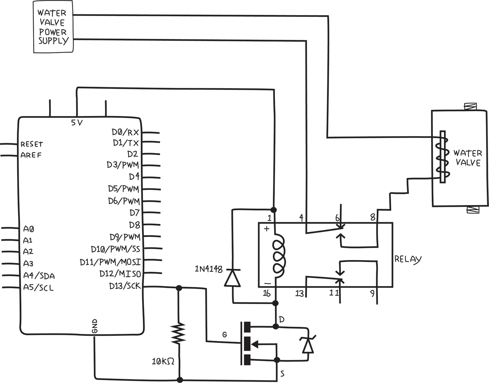
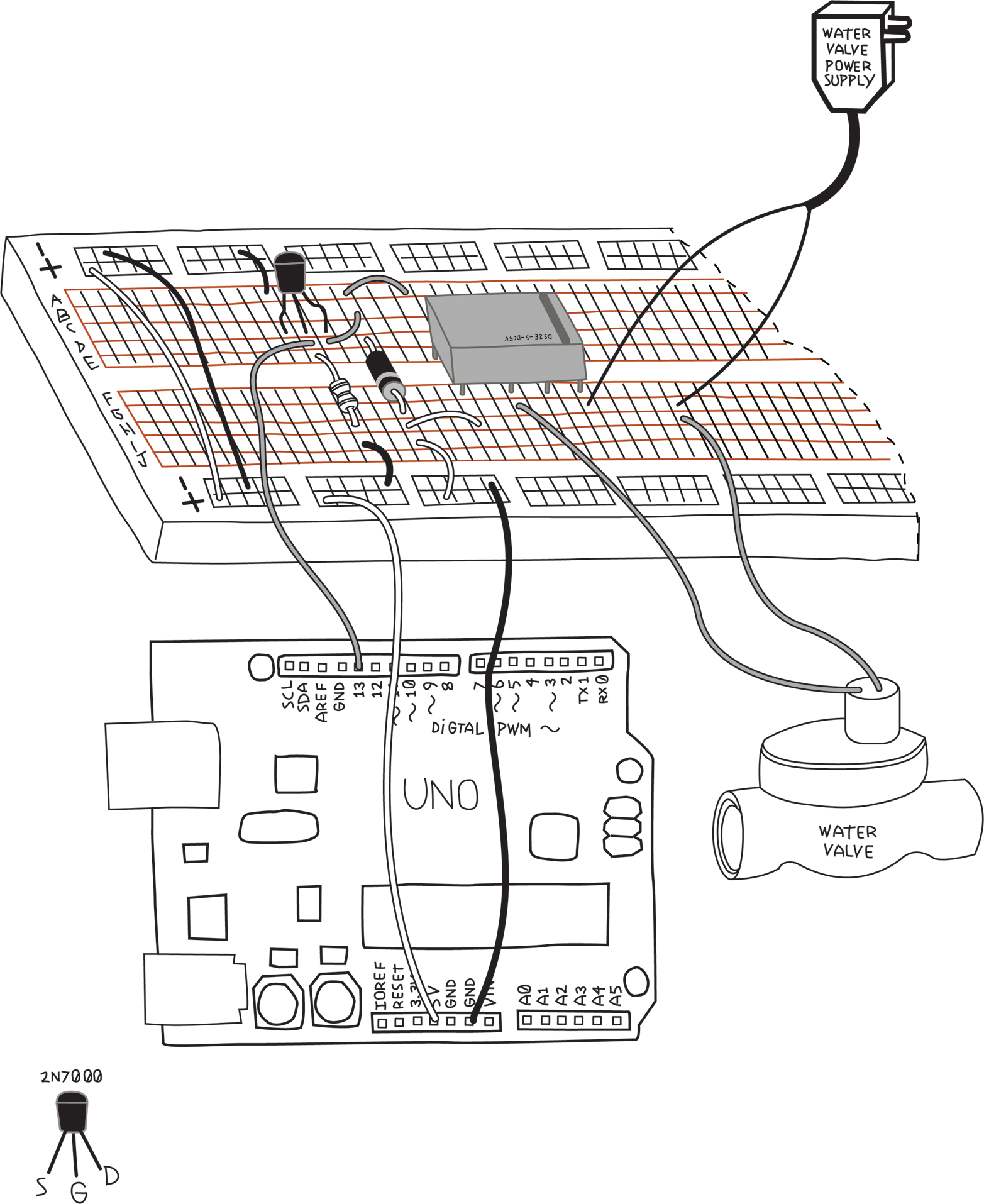
Figure 8-9 shows the circuit schematic with the water valve and power supply added.
And Figure 8-10 shows the pictorial circuit diagram of exactly the same circuit.
NOTE
The order of the water valve and the water valve power supply are changed in these two views. I did this to avoid having wires cross in the diagrams for clarity. When connecting a component and a power supply via a switch, the order doesn’t matter, as long as the switch controls whether the circuit is closed or open.
You can use the same Blink sketch; you should still hear the relay clicking. You might not hear the water valve clicking, because some water valves work only when they have water pressure inside of them. I was fortunate; my water valves made a very loud click when they were turned on.
What about the LEDs? They can be installed in a number of different places: at the digital outputs, at the MOSFET output, or at the relay output. When possible, I like to put the LED on the farthest point, to verify as much as possible, so let’s put it at the relay output. (If you want, you can put LEDs at all mentioned stages, making it very easy to spot exactly where the signal stops.)
What resistor should we use? This LED will be getting power from the water valve power supply. Most water valves seem to be either 12 or 24 volts. For safety, let’s design for a 24 V system, and if yours is a 12 V system, you can either reduce the value or have a slightly dimmer LED. It should still be quite visible.
LED resistor = (voltage of supply - voltage of LED)/(desired LED current)NOTE
If you’re uncertain about what value resistor to use when you’re using it to limit current, it’s always safer to choose a bigger-value resistor. The LED will be visible over quite a wide range of values, and, if it’s too dim, you can always reduce the resistance.
Most LEDs use about 2 volts and are safe below 30 mA, so we have R = (24-2)V/30mA = 733 ohms. You can safely round this up to 1K ohm; the result will be a little less current and a slightly dimmer LED.
But wait, in “Planning”, I told you that some water valves use AC, and then later in “Electronic Schematic Diagrams”, I told you that LEDs are polarized. Polarized means that the LEDs care which way the current flows, and AC means that the current changes direction all the time. Won’t that damage the LEDs? As it turns out, LEDs can withstand a certain amount of voltage in the wrong direction, but if the voltage is too high, the LED might be damaged. Fortunately, other diodes can withstand much higher voltages safely, so let’s use another three 1N4148 diodes to protect the LEDs, giving us an addition that takes the shopping list to revision 0.3:
- Change quantity of 1N4148 or similar diodes to six
- Specify the LED resistor value is 1K ohm
Figure 8-11 shows the circuit schematic with the LED and diode added. We’ve indicated the polarity of the water valve power supply and of the water valve, but this is relevant only if you have a DC system. If you have an AC system (which seems to be more common), these have no polarity.
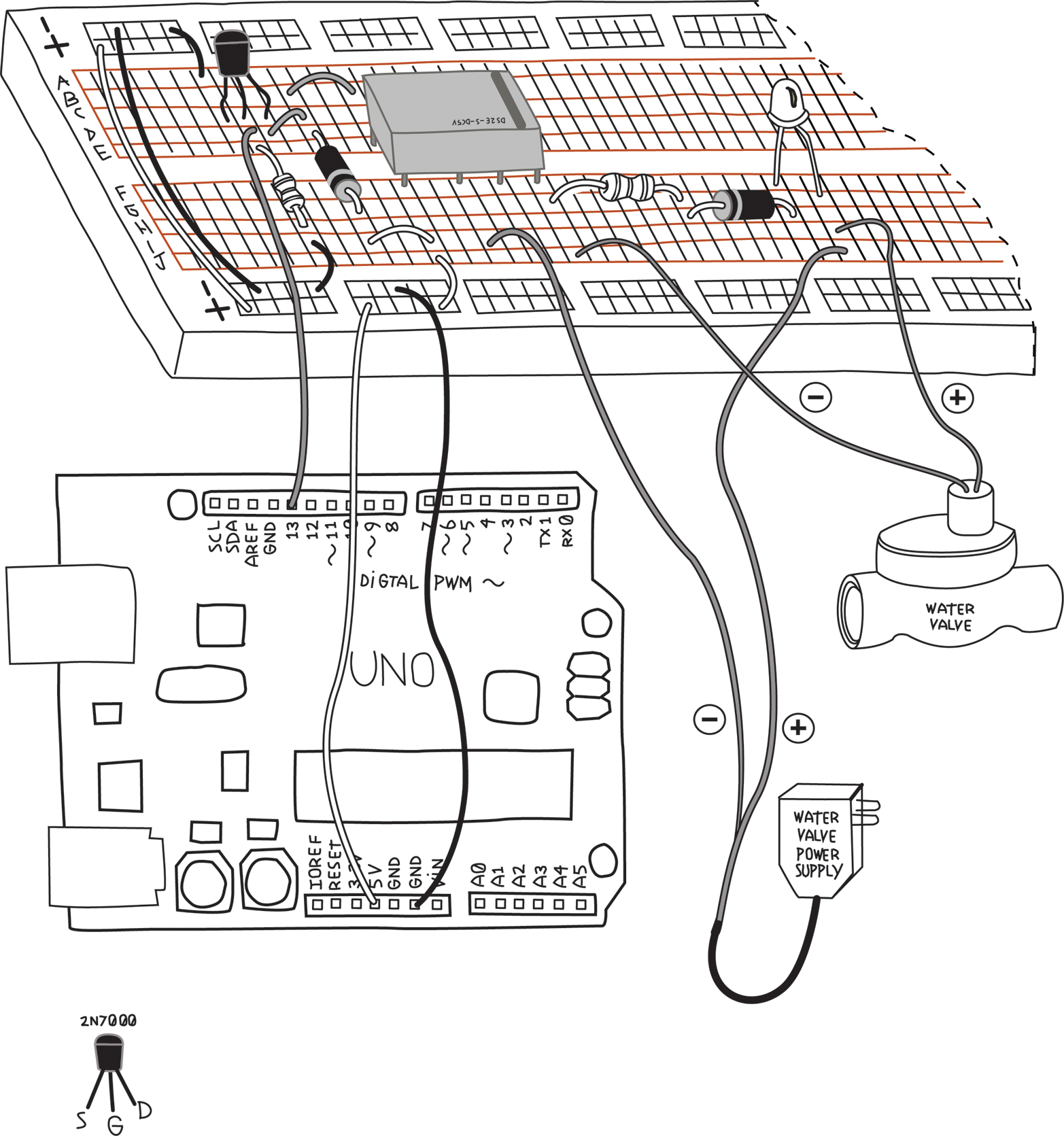
And Figure 8-12 shows the pictorial circuit diagram. I’ve left off the resistor values, so make sure you compare with the schematic and get the right resistor in the right place. Also pay attention to the LED and diode polarity—the LED anode connects to the water valve and the diode anode connects to the LED cathode.
Before you plug in the water valve power supply, double check your wiring, especially the relay connections. You don’t want the water valve power supply voltage to get into the Arduino, as it would almost certainly cause damage. Once again, run the Blink sketch. In addition to hearing the relay and possibly the valve clicking, you should see the LED light up.
Now that we have the relay and water valve figured out, let’s test the Temperature and Humidity Sensor.
Leave a Reply