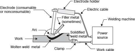
In electric arc welding, the heat required for melting the metal is generated by short-circuiting the electrodes. An intense heat is produced in the electric arc. Various types of mechanism are used to produce arc and to stabilize it. The selection of the mechanism, i.e., type of electric arc welding depends on the heat required to melt the metal. A schematic diagram of an electric arc welding is shown in Figure 20.34.
Mechanism of Arc Generation: When two electrodes are brought into contact with each other, electric spark is produced due to short-circuiting. Just after sparking, the electrodes are separated by 2–4 mm distance. The air gap between the electrodes is ionized due to flow of electron from cathode to anode and heavier positive ion from anode to cathode. Thus, arc is continued. The arc length is 0.6–0.8 times of the electrode diameter.
Modes of Metal Transfer in Arc Welding: There are numbers of forces dominant in arc welding, which are responsible for metal transfer. These forces are gravity force, surface tension, electromagnetic interaction, and hydrodynamic action.
Methods of Arc Generation:
- Between consumable electrode and workpiece.
- Between two non-consumable electrode and workpiece.
- Between a non-consumable electrode and workpiece.
Consumable electrode produces arc between electrode and work metal as well as works as a filler material, which fills the groove. During welding, it is consumed and its length decreases. But non-consumable electrode only produces the arc and additional filler material is used in the form of a rod, if it is required. When two non-consumable electrodes are used, the arc is produced between these electrodes and workpiece is not connected with the electric circuit. The workpiece and filler rod get heat for melting from the arc produced between these two electrodes. When a single, non-consumable electrode is used, the electrode and workpiece are connected with electric terminals.

Figure 20.34 Schematic Diagram of an Electric Arc Welding
Polarity: Polarity is concerned with the connection of the electrodes and work metal with particular electric terminals. Polarity is significant only in DC supply. Two types of polarity are used: straight polarity and reverse polarity
In the case of straight polarity, workpiece is connected with positive terminal and electrode is connected with negative terminal. About 70% of heat is produced at positive terminal only and 30% of heat is produced at negative terminal. If heat required for welding is large, straight polarity is used. In the case of reverse polarity, workpiece is connected with negative terminal and electrode is connected to positive terminal. Reverse polarity is used for large groove size, i.e., for more metal pilling. The difference between AC welding and DC welding is shown in Table 20.1.
Table 20.1 Differences Between AC and DC Welding
| AC welding | DC welding |
|---|---|
| AdvantagesEquipment of AC welding is less expansive, light in weight, easy maintainable, and having low operating cost.It has higher efficiency in comparison to DC welding (85%).It consumes low electrical energy per kg of metal deposited (3–4 kWh/kg).Minor magnetic arc blow problem occurs in comparison to DC welding. | AdvantagesIt has higher arc stability than that of AC welding.Bare electrode can be used easily.It has high power factor (0.6–0.7).Facility of change of polarity is done easily. |
| DisadvantagesIt has low power factor (0.3–0.4).For stability of the arc, voltage/frequency requirement of AC current is high.Only coated electrodes can be used with AC. If bared electrode is used, shielding gas must be there to keep the continuous ionized path of arc. | DisadvantagesIt has low efficiency (30–60%).It involves high cost of equipment and operation.It consumes high power (6–10 kWh/kg of metal deposited).Chances of magnetic arc blow problem are more. |
Magnetic Arc Blow Problem in DC Welding: Magnetic arc blow problem occurs when the magnetic flux surrounding the electrode and workpiece becomes unbalanced. In this problem, arc deflects from its path; it occurs generally at the end of workpiece or in the corner welding. Due to flow of electric current in the electrode and workpiece, a magnetic field is established around the workpiece and electrode in the direction perpendicular to the direction of flow of electric current. Due to defection in path of the arc, heat is not concentrated at the proper location. This problem is circumvented in AC welding as the polarity keeps changing and also the direction of magnetic flux.
Methods to Minimize Magnetic Arc Blow Problem
- Use AC in place of DC if it is possible.
- Reduce the current and the arc length.
- Ground connection of the welding joints.
- For reduction of backward arc blow, ground connection should be placed at the start of the weld.
- For reduction of forward arc blow, ground connection should be placed at the end of the weld.
Types of Electrodes: Two types of electrodes are used in electric arc welding as:
- Coated electrode.
- Bared electrode.
Coated electrode consists of coating of flux of various ingredients on its surface. Coating is generally used for arc stability. Normally, sticks of electrodes are available in the sizes of 3.2, 4, 5, 6, 8, 9, and 12 mm of diameter and 350 or 450 mm in length. In the case of coated electrodes, diameter is measured in the bare portion, i.e., without coating.
Leave a Reply