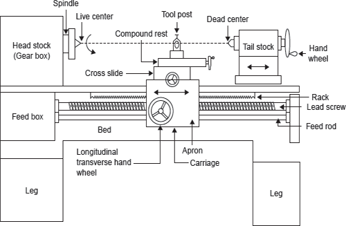
A lathe machine consists of a number of components. These components perform various functions, for example, facilitate variation in speed, hold the cutting tool, rigidly hold the job, provide end support to the job, automatic movement of tool, etc. A lathe with nomenclature of various parts is shown in Figure 19.5.

Figure 19.5 A Lathe with Nomenclature of Its Parts
Bed: All the fixed and moving parts of lathe are mounted on bed. It is made of cast iron in single piece, it may be in two or three pieces for large size lathe which are bolted together. It has v-ways for collection of chips produced during machining.
Head Stock: Head stock is housing of cone pulleys, back gear, main spindle, live centre, and feed reverse livers. It provides driving mechanism to the job and tool post, carriage, apron, etc.
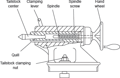
Tail Stock: The function of tail stock is to support the job at the end. It slides over the bed. It may have dead centre or live centre for point support to the job as per requirement. A tailstock is shown in Figure 19.6.

Figure 19.6 Tailstock of a Lathe
For tapping, drilling, or boring, a tape or drill/boring tool may be used in place of dead centre. The dead centre moves forward or backward with sleeve by rotating the hand wheel manually.
Carriage and Tool Post: It provides support to the tool post, cross slide, compound rest, apron, etc. The function of tool post is to hold cutting tool rigidly; tool post moves in both axial and transverse directions on compound rest. The function of swivel plate is to give angular direction to the tool post whereas the function of cross slide is to give the linear motion to the tool by rotating the attached hand wheel. Apron is a hanging part in front of the carriage. It is housing of gear trains and clutches. It gives automatic forward and reverse motion to the tool.
Legs: The legs provide rigid support to the entire machine tool. Both the legs are firmly secured to the floor by means of foundation bolts in order to prevent vibrations in the machine.
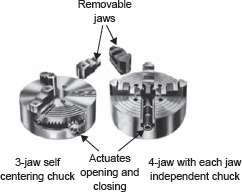
Chucks: The function of the chuck is to hold the job. There may be three- or four-jaw chuck as shown in Figure 19.7. In three-jaw chuck, all the jaws move inwards or outwards simultaneously and there is no problem of centring hence it is also known as universal chuck. Whereas in four-jaw chuck each jaw moves independently. It may accommodate irregular shape of job but there is problem of centring which is to be done manually. A magnetic chuck is also used to hold the job which works on the principle of electromagnetism.

Figure 19.7 Three- and Four-jaw Chucks
Leave a Reply