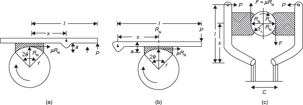
In this brake, a shoe or block is pressed against the drum. The force can be increased by using a lever as shown in Figure 16.8. The brake lining for friction is made of softer materials so that it can be replaced easily after wearing.

Figure 16.8 Block or Shoe Brakes
Let r = Radius of drum
μ = Coefficient of friction
RN = Normal reaction on the shoes
P = Force applied on lever
F = Frictional force
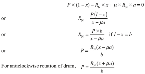
In Figure 16.8(a), taking moment about the pivot for clockwise rotation of drum

In Figure 16.8(b), taking moment about pivot for clockwise rotation of drum

Due to pressure applied by single shoe, there is a side thrust on the shaft of the drum. To counter balance the side thrust, two shoes may be used opposite to each other. In this case, braking torque becomes double which is shown in Figure 16.8 (c).
Example 16.7: A single block brake as shown in Figure 16.8 (b) has diameter of brake drum 1.2 m. It can withstand 250 N m torque at 500 rpm and coefficient of friction between block and drum is 0.3. Determine the force required to apply when the drum rotates in (a) clockwise direction, and (b) anticlockwise direction. The angle of contact is 2θ = 30° and x = 140 mm, a = 30 mm, l = 1,000 mm.
Solution:
For clockwise rotation

For anticlockwise rotation

Note: If angle of contact (2θ) is greater than 40° use μ′ in place of μ

Example 16.8: In a double block spring loaded brake as shown in Figure 16.8 (c) following dimensions have been given: drum diameter = 600 mm, angle of contact (2θ) = 100°, coefficient of friction (μ) = 0.3, force applied on the spring = 6 kN, x = 0.5 m, l = 1 m, c = 0.1 m. Find the braking torque applied.
Solution:

For left side block
Taking moment about o


Leave a Reply