Radioactive materials is taken into the body are removed by two mechanisms: physical decay and biological processes, each with its own characteristic half‐life. The combined removal by these two mechanisms is known as the effective half‐life, Teff, which is determined by
The effective half‐life is always smaller than either the biological or radiological half‐life. Or the biological half‐life is very much smaller than the other, it will approximate the effective half‐life.
EXAMPLE 5.19 BIOLOGICAL HALF‐LIFE
A worker inhales a radionuclide in a single acute exposure. Body fluid sample shows a half‐life of 6.1 days. The nuclide has a decay constant of 0.08/day. What is the biological half‐life in the worker?
SOLUTION
The radiological half‐life is determined by the Eq. (5.17):

The biological half‐life is obtained from Eq. (5.18):


Radiation Protection Principles
The basic radiation exposure limit is 5 rem (50 mSv) annually, referred to as the maximum permissible dose (MPD). Doses from all sources, whether from internal or external radiations, are included. There are specific annual limit on intake (ALI) established for various radionuclides. Intake of one ALI will produce an MPD equivalent of 5 rem (50 mSv). Permissible air concentration for specific radionuclides are obtained by dividing the ALI by the annual breathing rate and converted to activity per volume of air. This is known as the derived air concentration which is commonly expressed in units of μCi/ml in the old system or Bq/m3 in the SI unit.
The fundamental decay law described above has the same form as the shielding equation for X‐rays and gamma rays. The basic shielding or attenuation may be expressed as follows:
(5.19)![]()
where
- dI = reduction of radiation
- I0 = incident radiation
- μ = proportionality constant
- dx = thickness of absorber or shielding material
Integrating yields
(5.20)![]()
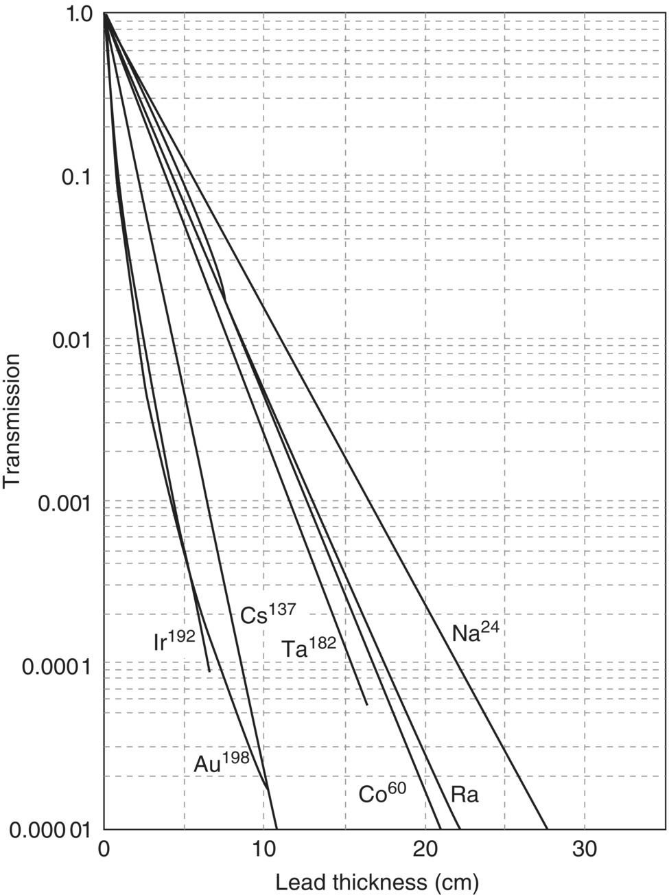
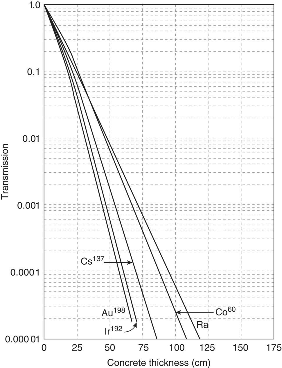
The ratio I/I0 is sometimes called the transmission. The linear attenuation coefficient, μ, is a specific function of the energy of the photons and the shielding material, and it is usually given in units of reciprocal centimeter. This is the linear attenuation coefficient divided by the density and symbolized by μ/x. If the mass attenuation coefficient is used, the thickness of the shielding material has to be expressed in comparable reciprocal units, which are obtained by multiplying the linear thickness by the density. Tables and graphs are available that give values of μ determined experimentally or that give transmission values for varying thickness or different shielding materials (Figures 5.17 and 5.18).
Reduction of External Radiation Hazards
Three fundamental methods are employed to reduce external radiation hazards: shielding, distance, and reduction of exposure time.
Shielding
Shielding is one of the most important methods for radiation protection. It is accomplished by placing some absorbing material between the source and the person to be protected. Radiation is attenuated in the absorbing medium. Typical shielding materials used are lead, concrete, and iron, depending on the sources of radiation.
Distance
Distance is not only very effective, but also in many instances the most easily applied principle of radiation protection. Beta particles of a single energy have a finite range in air. Sometimes the distance afforded by the use of remote control handling devices will supply complete protection.
The inverse square law for reduction of radiation intensity applies for point sources of X‐rays, gamma, and neutron radiation. The inverse square law states that radiation intensity from a point varies inversely as the square of the distance from the source.


where I1 is the radiation intensity at distance R1 from the source, and I2 is the radiation intensity at distance R2 from the source. The inverse law does not apply to extended sources or to radiation fields from multiple sources.
Reduction of Exposure Time
By limiting the duration of exposure to all radiation sources and by providing ample recuperative time between exposures, the untoward effects of radiation can be minimized. In emergency situations, it may occasionally be necessary to work in areas of very high dose rates. This can be done with safety by limiting the total exposure time so that the average permissible value for a day based on the radiation protection guide dose of 1 × 10⁻³ Gy (0.1 rad) per week is not exceeded.
EXAMPLE 5.20 LEAD THICKNESS
What thickness (in cm) of lead is required to shield a 60Co source so that the transmission is reduced to 99.5%?
SOLUTION
Given:
- 60Co source, transmission reduction of 99.5% required using lead shield
- Compute transmission allowed
- 1.000 − 0.995 = 0.005
- From Figure 5.17 using 60Co line Lead thickness required = 8.5 cm(Allow some tolerance for graph reading)
EXAMPLE 5.21 CONCRETE THICKNESS
What is the equivalent thickness (in cm) of concrete to accomplish the same shielding as the lead in Problem 5.20?
SOLUTION
- Using a transmission of 0.005 from Problem 5.20 and 60Co line in Figure 5.18Concrete thickness = 53 cm(Allow some tolerance for graph reading).
EXAMPLE 5.22 RADIOACTIVE DECAY
When an X‐ray unit is operated at 70 kV and 5 mA, it produces an intensity of I1 per minute at 1.0 m from the source. What intensity will it produce at 2.0 m from the source?
SOLUTION
Given:
X‐ray unit operated at 70 kVp and 5 mA produces intensity of I1 per minute at 1.0 m from source
Apply Eq. (5.21)
 =
= 
 =
= 
- I2 =
 I1 = 0.25I1
EXAMPLE 5.23 RADIOACTIVE DECAY
As described earlier, exponential first‐order decay can be described using either a reaction rate coefficient (k) or a half‐life (τ). The equation that relates these two parameters is as follows:

Exponential decay can be expressed by the following equation:

where
- k = reaction rate coefficient (per time)
- N0 = initial amount
- N = amount at time t
Determine how much of a 100‐g sample of P0‐210 is left after 5.52 days using:
- The reaction rate coefficient
- The half‐life
- Calculate the percent error between the two methods
The half‐life for Po‐210 is 1.38 days.
SOLUTION
- Determine the reaction rate coefficient:k = 0.693/τ = 0.693/1.38 day = 0.502/dayThe amount of substance left after 5.52 days is as follows:N = N0е−kt = 100е−0.502 × 5.52 = 6.26 g
- The first step is to determine how many half‐lives the 100 g sample has undergone in the given time period:Number of half‐lives = (5.52 days)/(1.38 days) = 4.0Therefore, in a 5.52 period, the 100 g sample has undergone 4 half‐lives.The amount of the substance left after one half‐life is calculated as follows:(0.5)1(100 g) = 50 gTherefore, the amount of substance left after four half‐lives is(0.5)4(100 g) = 6.25 g
- Since the two equations are, in principle, identical to each other, there is no difference between the two values. The small difference between the two results arises because of round‐off errors.


Leave a Reply