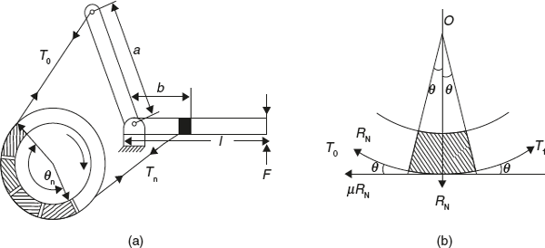
This is combination of band and block brake. A number of blocks are mounted on the drum and inside the band and brake is applied by pressing the blocks against the drum with the help of band. To increase the effectiveness of brake, blocks are used under the band since blocks have higher coefficient of friction.
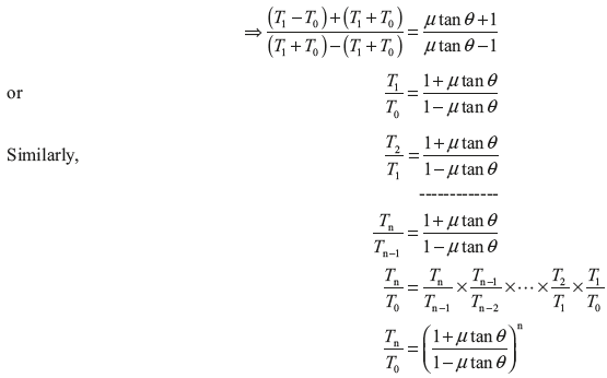
Let T0 = Tension in band on slack side
T1 = Tension in band after one block
———————————
———————————
Tn = Tension in band after nth block
μ = Coefficient of friction
Forces on block are shown in Figure 16.10 (b).

Figure 16.10 Band and Block Brake


Exercise 16.10: There are 15 blocks in a band and block brake. Each block subtends 30° angle at centre. The data given for the brake are radius of drum = 250 mm, block thickness = 50 mm, coefficient of friction = 0.3, a = 500 mm, b = 40 mm, F = 300 N, l = 1,000 mm. Calculate the braking torque.
Solution:

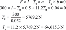
Here, a > b, therefore, F should be downward and drum rotates in clockwise direction. Taking moment about fulcrum, we get

Braking torque, TB = (Tn − T0) × (r + t) = (64,615.3 − 5,769.2) (0.125 + 0.025) = 8,826.9 N m
16.10.4 Internal Expanding Shoe Brake
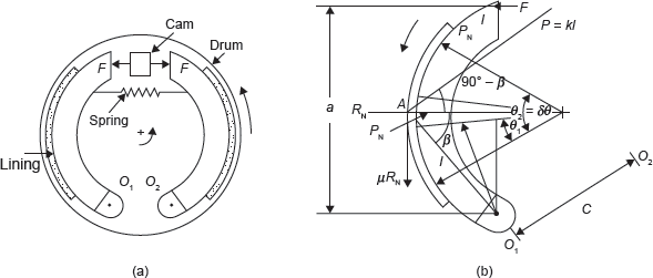
Internal expanding shoe brake has two semicircular shoes which are lined with friction materials. The outer diameter of shoe is less than inner diameter of drum, so that the drum can rotate freely. When brake is applied, the shoes expand and press the inner surface of the drum and resist the motion. Working of internal expanding shoe brake is shown in Figure 16.11.

Figure 16.11 Internal Expanding Shoe Brake
It is used in automobile. It is self-energizing and good heat dissipative. A hydraulic pressure is generated in piston–cylinder arrangement. This hydraulic force is applied equally on both the shoes in the direction shown in Figure 16.11 (a). For counterclockwise rotation of the drum the left shoe is primary leading shoe while the right shoe is secondary or trailing shoe. Pressure at any point A on the surface will be proportional to its distance l from the pivots.

The normal pressure will be maximum when θ is equal to 90°. Thus,
![]() = Maximum pressure interfaced by leading shoe.
= Maximum pressure interfaced by leading shoe.
PN = K2 sin θ =
Let B = width of brake lining
μ = coefficient of friction
Consider a small element of brake lining the leading shoe that makes an angle δθ at the centre.

Taking moment about fulcrum O1, we get


Similarly, taking moment about fulcrum O2, we get

Here, t superscript is used for trailing shoe.
Thus, the maximum pressure intensities on leading and trailing shoes can be determined.
Braking torque,

Leave a Reply