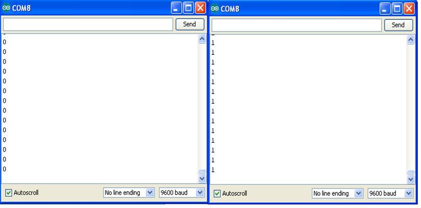
Tilt control switching can be used in a variety of human machine control and physical computing applications. In the theater, electromechanical puppets are often controlled using electronic sensors and servo motors. The tilt control switch project you built can be used as a simple animatronic controller. Example 3-2 shows an improved Arduino sketch that limits the servo motor rotation to 90° and adds Serial Monitor output for displaying information about the tilt control switch. Figure 3-6 shows the tilt control switch digital data.
TECH NOTE
Physical computing allows people to interact with objects using electronics, software, and sensors.

Figure 3-6. Digital data from tilt control switch: open tilt control switch (left), closed tilt control switch (right)
Example 3-2. Tilt Control Switch with Serial Monitor
/* This sketch controls a servo motor using a tilt control switch!
 * Serial Monitor displays digital data from Tilt Control Switch.
 *
 * 15 December 2012
 * by Don Wilcher
 *
 */

#include<Servo.h> // include Servo library
int inPin = 2;   //  the Arduino input pin tilt control switch is wired to D2
int reading;    //   the current reading from the input pin
Servo myservo; //    create servo motor object

void setup()
{
    myservo.attach(9);      // attach servo motor to pin 9 of Arduino
    pinMode(inPin, INPUT); //  make pin 2 an input
    Serial.begin(9600);   //   open communication port
}

void loop()
{
    reading = digitalRead(inPin);   // store digital data in variable
    if(reading == HIGH) {           // check it against target value (HIGH)

        myservo.write(90);          // if digital data equals target value,
                                   //  servo motor rotates 90 degrees
        Serial.println(reading);  //   print tilt control switch digital data
        delay(15);               //    wait 15ms for rotation
    }
    else {                         // if it's not equal to target value...
        myservo.write(0);         //  rotate servo motor to 0 degrees
        Serial.println(reading); //   print tilt control switch digital data
        delay(15);              //    wait 15ms for rotation
    }
}
Experiment with the different rotation angle values and observe the servo motor’s behavior. Happy puppetry!
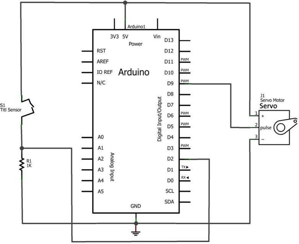
The block diagram in Figure 3-7 shows the electronic component blocks and the electrical signal flow for the Tilt Sensing Servo Motor Controller. A Fritzing electronic circuit schematic diagram of the controller is shown in Figure 3-8. Electronic circuit schematic diagrams are used by electrical/electronic engineers to design and build cool electronic products for society.

Figure 3-7. Tilt Sensing Servo Motor Controller block diagram
TECH NOTE
Always document your experiments and design changes in a lab notebook in case you develop that million dollar idea!
OBSERVING THE SWITCH’S BEHAVIOR
If you have or know someone who has a DMM (digital multimeter), attach your tilt control switch to it. Set the DMM to read resistance. By changing the orientation of the tilt control switch, you will see the internal pins open and close based on the changing resistance value. A closed tilt control switch has a DMM resistance reading of zero ohms. An open tilt control switch has an infinite resistance value displayed on the DMM. The pins’ switching conditions are used to rotate a servo motor. In the Tilt Sensing Servo Motor Controller project, directional movement will occur by orientation of the sensor circuit.
Note that an infinite resistance reading may be displayed as O or 1 on a DMM.

Figure 3-8. Tilt Sensing Servo Motor Controller circuit schematic diagram: orange wire (D9), red wire (+5V), and brown wire (GND)
Leave a Reply