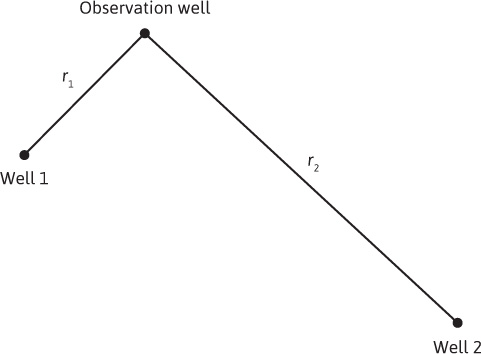
Earlougher and others have discussed the application of the principle of superposition to fluid flow in reservoirs.3,12,13,14 This principle allows the use of the constant rate, single-well equations that have been developed earlier in this applies them to a variety of other cases. To illustrate the application, the solution to Eq. (8.38), which is a linear, second-order differential equation, is examined. The principle of superposition can be stated as follows: The addition of solutions to a linear differential equation results in a new solution to the original differential equation. For example, consider the reservoir system depicted in Fig. 8.16. In the example shown in Fig. 8.16, wells 1 and 2 are opened up to their respective flow rates, q1 and q2, and the pressure drop that occurs in the observation well is monitored. The principle of superposition states that the total pressure drop will be the sum of the pressure drop caused by the flow from well 1 and the pressure drop caused by the flow from well 2:
Δpt = Δp1 + Δp2

Figure 8.16 Two flowing-well reservoir system to illustrate the principle of superposition.
Each of the individual Δp terms is given by Eq. (8.39), or

To apply the method of superposition, pressure drops or changes are added. It is not correct simply to add or subtract individual pressure terms. It is obvious that if there are more than two flowing wells in the reservoir system, the procedure is the same, and the total pressure drop is given by the following:

where N equals the number of flowing wells in the system. Example 8.2 illustrates the calculations involved when more than one well affects the pressure of a point in a reservoir.
Example 8.2 Calculating Total Pressure Drop
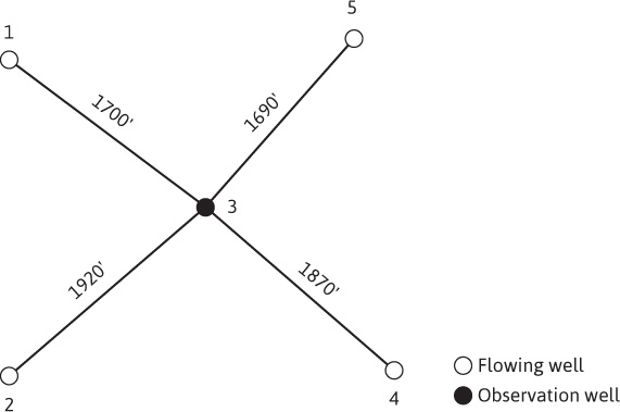
For the well layout shown in Fig. 8.17, calculate the total pressure drop as measured in the observation well (well 3) caused by the four flowing wells (wells 1, 2, 4, and 5) after 10 days. The wells were shut in for a long time before opening them to flow.

Figure 8.17 Well layout for Problem 8.2.
Given
The following data apply to the reservoir system:
μ = 0.40 cp
Bo = 1.50 bbl/STB
k = 47 md
h = 50 ft
φ = 11.2%
ct = 15 × 10–6 psi–1

Solution
The individual pressure drops can be calculated with Eq. (8.39), and the total pressure drop is given by Eq. (8.54). For well 1,

From Fig. 8.12,
– Ei(– 0.164) = 1.39
Therefore,
Δp1 = 4.78(1.39) = 6.6 psi
Similarly, for wells 2, 4, and 5,
Δp2 = 4.87[– Ei(– 0.209)] = 5.7 psi
Δp4 = 5.14[– Ei(– 0.198)] = 6.4 psi
Δp5 = 4.69[– Ei(– 0.162)] = 6.6 psi
Using Eq. (8.54) to find the total pressure drop at the observation well (well 3), the individual pressure drops are added together to give the total:
Δpt = Δp1 + Δp2 + Δp4 + Δp5
or
Δpt = 6.6 + 5.7 + 6.4 + 6.6 = 25.3 psi
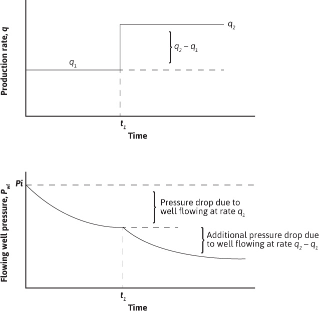
The superposition principle can also be applied in the time dimension, as is illustrated in Fig. 8.18. In this case, one well (which means the position where the pressure disturbances occur remains constant) has been produced at two flow rates. The change in the flow rate from q1 to q2 occurred at time t1. Figure 8.18 shows that the total pressure drop is given by the sum of the pressure drop caused by the flow rate, q1, and the pressure drop caused by the change in flow rate, q2 – q1. This new flow rate, q2 – q1, has flowed for time t – t1.

Figure 8.18 Production rate and pressure history for a well with two flow rates.
The pressure drop for this flow rate, q2 – q1, is given by

As in the case of the multiwell system just described, superposition can also be applied to multirate systems as well as the two rate examples depicted in Fig. 8.18.
Leave a Reply