As you learned in the previous section, Arduino is able to detect whether there is a voltage applied to one of its pins and report it through the digitalRead() function. This kind of either/or response is fine in a lot of applications, but the light sensor that we just used is able to tell us not only whether there is light, but also how much light there is. This is the difference between an on/off or digital sensor (which tells us whether something is there or not) and an analogue sensor, which can tell us how much of something there is.
In order to read this type of sensor, we need to use a special Arduino pin.
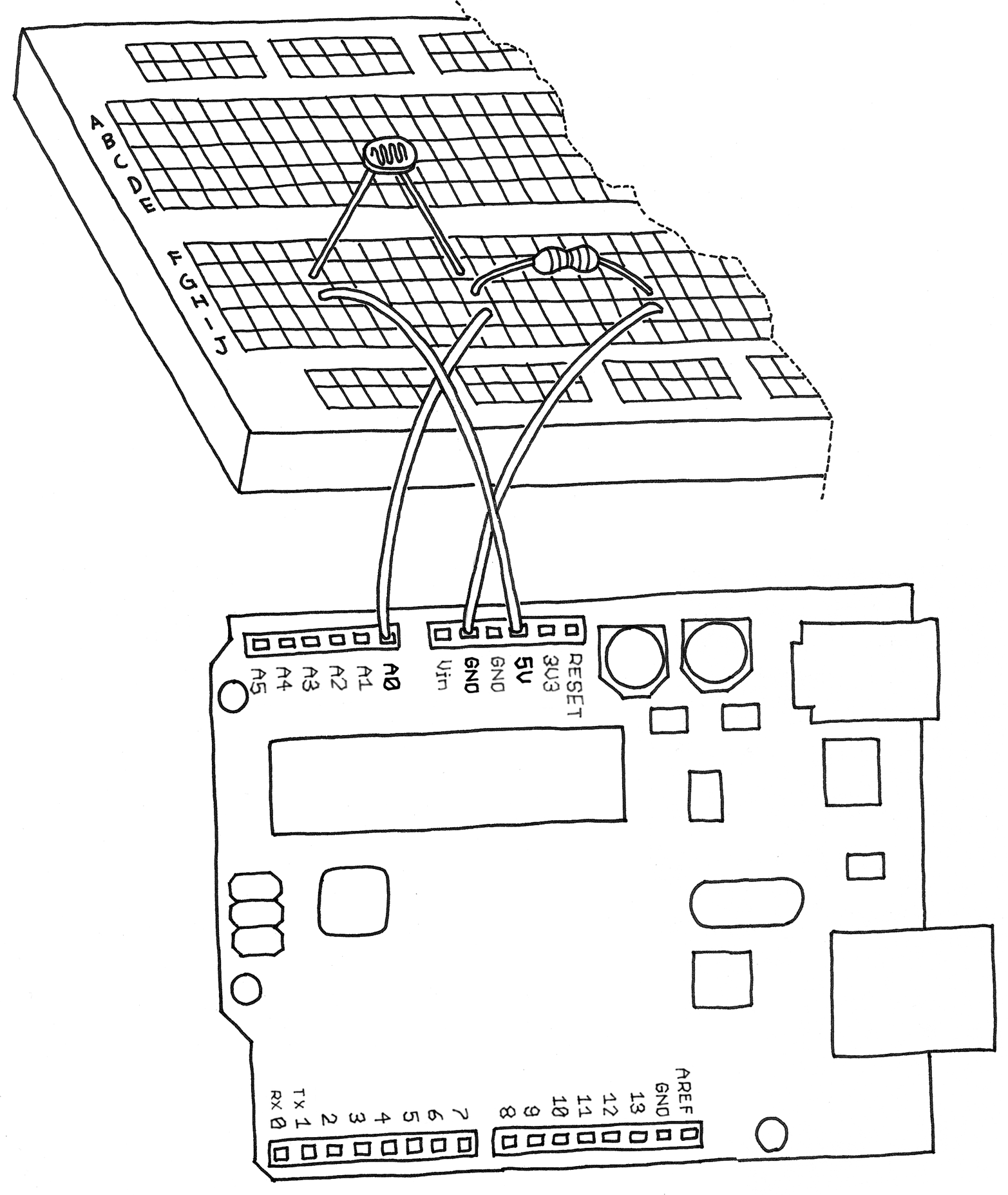
Turn your Arduino around so it matches Figure 5-6.
In the top-left part of the board, you’ll see six pins marked Analog In; these are special pins that not only can tell you whether there is a voltage applied to them, but also can measure the amount of that voltage by using the analogRead() function. The analogRead() function returns a number between 0 and 1023, which represents voltages between 0 and 5 volts. For example, if there is a voltage of 2.5 V applied to pin number 0, analogRead(0) returns 512.
If you now build the circuit that you see in Figure 5-6, using a 10 K ohm resistor, and run the code listed in Example 5-3, you’ll see the onboard LED blinking at a rate that depends on the amount of light that shines on the sensor.

Example 5-3. Blink LED at a rate specified by the value of the analogue input
const int LED = 13; // the pin for the LED

int val = 0;   // variable used to store the value
               // coming from the sensor
void setup() {
  pinMode(LED, OUTPUT); // LED is as an OUTPUT

  // Note: Analogue pins are
  // automatically set as inputs
}

void loop() {

  val = analogRead(0); // read the value from
                       // the sensor

  digitalWrite(LED, HIGH); // turn the LED on

  delay(val); // stop the program for
              // some time

  digitalWrite(LED, LOW); // turn the LED off

  delay(val); // stop the program for
              // some time
}
Now add an LED to pin 9 as we did before, using the circuit shown in Figure 5-4. Because you already have some stuff on the breadboard, you’ll need to find a spot on the breadboard where the LED, wires, and resistor won’t overlap with the LDR circuit. You may have to move some things around, but don’t worry, this is good practice because it helps your understanding of circuits and the breadboard.
When you are done adding the LED to your LDR circuit, type in Example 5-4 and upload it to your Arduino.
Example 5-4. Set the LED to a brightness specified by the value of the analogue input
const int LED = 9;  // the pin for the LED

int val = 0;   // variable used to store the value
               // coming from the sensor

void setup() {

  pinMode(LED, OUTPUT); // LED is as an OUTPUT

  // Note: Analogue pins are
  // automatically set as inputs
}

void loop() {

  val = analogRead(0); // read the value from
                       // the sensor
  analogWrite(LED, val/4); // turn the LED on at
                           // the brightness set
                           // by the sensor

  delay(10); // stop the program for
             // some time
}
Once it’s running, cover and uncover the LDR and see what happens to the LED brightness.
As before, try to understand what’s going on. The program is really very simple, in fact much simpler than the previous two examples.
NOTE
We specify the brightness of the LED by dividing val by 4, because analogRead() returns a number up to 1023, and analogWrite() accepts a maximum of 255. The reason for this is that it is always desireable to read analog sensors with as much precision as possible, while our eyes can’t detect more subtle differences in the brightness of an LED. If you are wondering why analogRead() doesn’t return an even bigger range of numbers, it’s because that would occupy more space on the piece of silicon at the heart of the microcontroller, space that would have to come at the price of some other feature. Designing microntrollers is always a careful balance of features, space, heat, cost, and the number of pins.
Leave a Reply