Although the pore spaces within rocks seldom resemble straight, smooth-walled capillary tubes of constant diameter, it is often convenient and instructive to treat these pore spaces as if they were composed of bundles of parallel capillary tubes of various diameters. Consider a capillary tube of length L and inside radius ro, which is flowing an incompressible fluid of μ viscosity in laminar or viscous flow under a pressure difference of (p1 – p2). From fluid dynamics, Poiseuille’s law, which describes the total flow rate through the capillary, can be written as

Darcy’s law for the linear flow of incompressible fluids in permeable beds, Eq. (8.7), and Poiseuille’s law for incompressible fluid capillary flow, Eq. (8.15), are quite similar:

Writing ![]() for area in Eq. (8.7) and equating it to Eq. (8.17),
for area in Eq. (8.7) and equating it to Eq. (8.17),

Thus the permeability of a rock composed of closely packed capillaries, each having a radius of 4.17(10)–6 ft (0.00005 in.), is about 200 md. And if only 25% of the rock consists of pore channels (i.e., it has 25% porosity), the permeability is about one-fourth as large, or about 50 md.
An equation for the viscous flow of incompressible wetting fluids through smooth fractures of constant width may be obtained as

In Eq. (8.19), W is the width of the fracture; Ac is the cross-sectional area of the fracture, which equals the product of the width W and lateral extent of the fracture; and the pressure difference is that which exists between the ends of the fracture of length L. Equation (8.19) may be combined with Eq. (8.7) to obtain an expression for the permeability of a fracture as

The permeability of a fracture only 8.33(10)–5 ft wide (0.001 in.) is 53,500 md.
Fractures and solution channels account for economic production rates in many dolomite, limestone, and sandstone rocks, which could not be produced economically if such openings did not exist. Consider, for example, a rock of very low primary or matrix permeability, say 0.01 md, that contains on the average a fracture 4.17(10)–4 ft wide and 1 ft in lateral extent per square foot of rock. Assuming the fracture is in the direction in which flow is desired, the law of parallel flow, Eq. (8.15), will apply, and

8.4.6 Radial Flow of Incompressible Fluid, Steady State
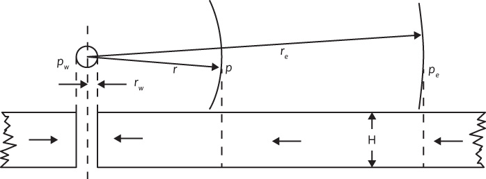
Consider radial flow toward a vertical wellbore of radius rw in a horizontal stratum of uniform thickness and permeability, as shown in Fig. 8.9. If the fluid is incompressible, the flow across any circumference is a constant. Let pw be the pressure maintained in the wellbore when the well is flowing q STB/day and a pressure pe is maintained at the external radius re. Let the pressure at any radius r be p. Then at this radius r,


Figure 8.9 Representation of radial flow toward a vertical well.
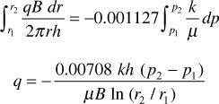
where positive q is in the positive r direction. Separating variables and integrating between any two radii, r1 and r2, where the pressures are p1 and p2, respectively,

The minus sign is usually dispensed with, for where p2 is greater than p1, the flow is known to be negative—that is, in the negative r direction, or toward the wellbore:

Frequently the two radii of interest are the wellbore radius rw and the external or drainage radius re. Then

The external radius is usually inferred from the well spacing. For example, a circle of 660 ft radius can be inscribed within a square 40 ac unit, so 660 ft is commonly used for re with 40 ac spacing. Sometimes a radius of 745 ft is used, this being the radius of a circle 40 ac in area. The wellbore radius is usually assigned from the bit diameter, the casing diameter, or a caliper survey. In practice, neither the external radius nor the wellbore radius is generally known with precision. Fortunately, they enter the equation as a logarithm, so that the error in the equation will be much less than the errors in the radii. Since wellbore radii are about 1/3 ft and 40 ac spacing (rc = 660 ft) is quite common, a ratio 2000 is quite commonly used for re/rw. Since ln 2000 is 7.60 and ln 3000 is 8.00, a 50% increase in the value of re/rw gives only a 5.3% increase in the value of the logarithm.
The external pressure pe used in Eq. (8.21) is generally taken as the static well pressure corrected to the middle of the producing interval, and the flowing well pressure pw is the flowing well pressure also corrected to the middle of the producing interval during a period of stabilized flow at rate q. When reservoir pressure stabilizes as under natural water drive or pressure maintenance, Eq. (8.21) is quite applicable because the pressure is maintained at the external boundary, and the fluid produced at the well is replaced by fluid crossing the external boundary. The flow, however, may not be strictly radial.
Leave a Reply