You already know enough to build an interactive lamp, but so far the result is a little boring, because the light is only either on or off. A fancy interactive lamp needs to be dimmable. To solve this problem, we can use a little trick that makes a lot of things possible, such as TV or cinema. This trick is called Persistence of Vision, or POV. POV takes advantage of the fact that our eyes can’t “refresh” what they see more than about 10 times per second. If what we’re looking at changes more rapidly than that, the eye “blurs” one image into the other, creating the illusion — some say “interpretation” — of movement.
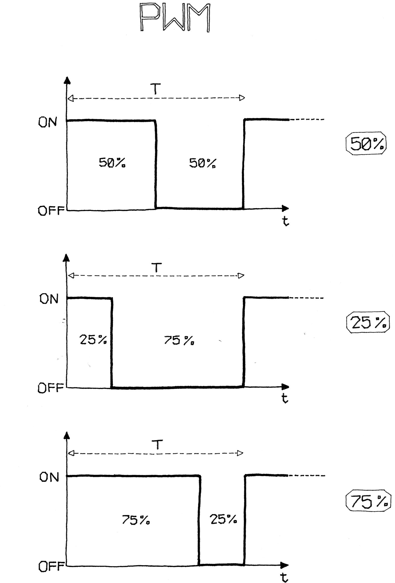
If you reduce the numbers in the delay function until you don’t see the LED blinking anymore, you will notice that the LED seems to be dimmer than its normal brightness. If you experiment with this, you will notice that if you make the on delay different from the off delay, you can make the LED appear brighter by leaving it on for longer, and you can make the LED seem to be dimmer by leaving it off for longer. This technique is called pulse-width modulation, or PWM, because you are changing the LED’s brightness by modulating (or changing) the width of the pulse. Figure 5-3 shows how this works. This works because thanks to persistence of vision, our eyes can’t see the distinct changes in the LED, because they’re happening too fast.
Pulse Width Modulation works with some devices other than an LEDs. For example, you can change the speed of a motor in the same way. In this case, it isn’t our eyes that allow this to happen, but rather the motor itself, because it can’t start or stop turning instantly. It takes a small amount of time for the motor’s rotor to speed up and slow down. If we change the output (using digitalWrite()) faster than the motor can respond, it ends up turning at some intermediate speed, depending on how much time it’s turned on, and how much time it’s turned off.
While this trick is very useful, you probably felt that controlling the LED brightness by fiddling with the delays in your code is a bit inconvenient. Even worse, as soon as you want to read a sensor, send data on the serial port, or do almost anything else, the LED brightness will change, because any extra lines of code you add will take time to execute, which will change the amount of time the LED is on or off.
Luckily, the microcontroller used by your Arduino includes a special piece of hardware called a timer/counter. Timer/counters run independently of whatever program your microcontroller is performing and can very efficiently blink your LEDs while your sketch does something else. On the Uno, this hardware is implemented on pins 3, 5, 6, 9, 10, and 11. Specifically, once set up correctly, the timer/counters can automatically turn on a pin for a certain amount of time, and then turn it off for a different amount of time, all without affecting your program. If you draw a graph of the voltage at the pin, you will see that the pulses can vary in width; thus this technique is called Pulse Width Modulation, or PWM.

The function that handles PWM on the Arduino is called analogWrite(). analogWrite() takes a value between 0 and 255, where 255 means full brightness and 0 means completely off.For example, writing analogWrite(9,50) will set the brightness of an LED connected to pin 9 to quite dim, while writing analogWrite(9,200) will set the brightness of the LED to quite bright. If you connect a motor to pin 9, analogWrite(9,50) will move the motor quite slowly, while writing analogWrite(9,200) will make the motor move much faster.
NOTE
Having multiple PWM pins is very useful. For example, if you buy an RGB LED (an LED that can emit red, green, and blue light in different intensities), you can adjust each value to make light of any colour.
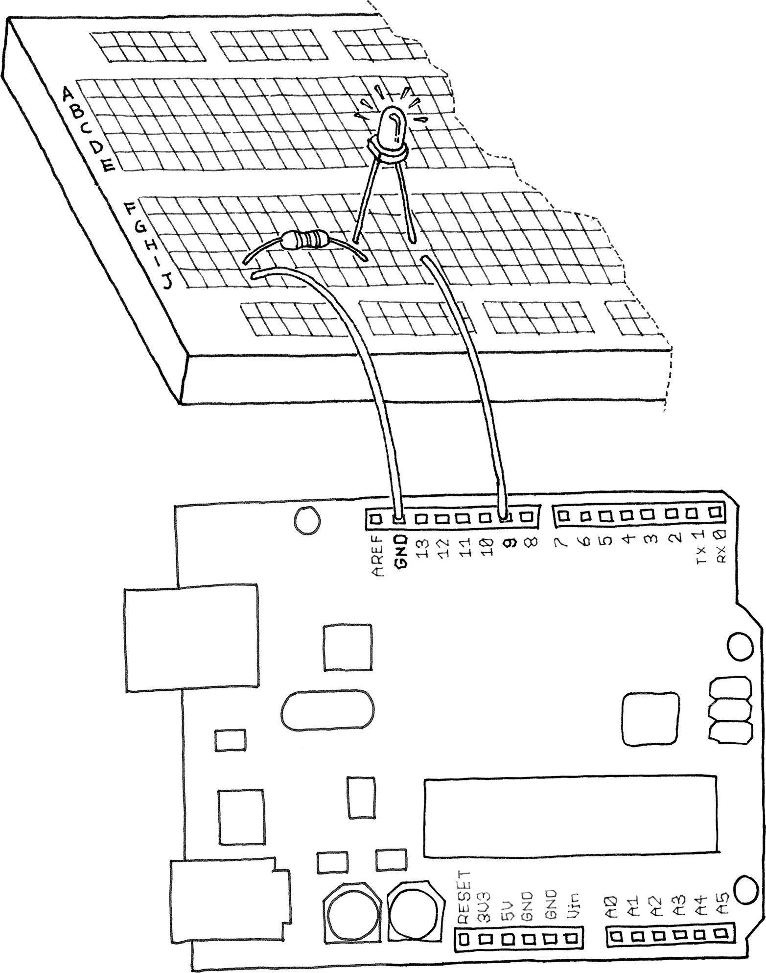
Let’s try it out. Build the circuit that you see in Figure 5-4. You’ll need an LED of any colour and some 220-ohm resistors1.
Note that LEDs are polarized, which means they care which way the electric current goes through them. The long lead indicates the anode, or positive lead, and in our case should go to the right, which connects it to pin 9 of the Arduino. The short lead indicates the cathode, or negative lead, and in this case it should go to the left, connecting it to the resistor.
Most LEDs also have a flattened edge on the cathode side, as shown in the figure. An easy way to remember this is that the flat part looks like a minus sign, and that the short lead has had something subtracted from it.
As we mentioned in “Blinking an LED”, you should always use a resistor with an LED to prevent burning out the LED. Any value between 220 ohm resistor (red-red-brown) and 1000 ohm (brown-black-red) should be fine.
Then, create a new sketch in Arduino with the code shown in Example 5-1.

Example 5-1. Fade an LED in and out, like on a sleeping Apple computer
const int LED = 9; // the pin for the LED
int i = 0;         // We'll use this to count up and down

void setup() {
  pinMode(LED, OUTPUT); // tell Arduino LED is an output
}

void loop(){

  for (i = 0; i < 255; i++) { // loop from 0 to 254 (fade in)
    analogWrite(LED, i);      // set the LED brightness
    delay(10); // Wait 10ms because analogWrite
               // is instantaneous and we would
               // not see any change with no delay
  }

  for (i = 255; i > 0; i--) { // loop from 255 to 1 (fade out)
    analogWrite(LED, i); // set the LED brightness
    delay(10);           // Wait 10ms
  }

}
Upload the sketch, and the LED will fade up and then fade down continuously. Congratulations! You have replicated a fancy feature of a laptop computer.
Maybe it’s a bit of a waste to use Arduino for something so simple, but you can learn a lot from this example.
As you learned earlier, analogWrite() changes the LED brightness. The other important part is the for loop: it repeats the analogWrite() and the delay() over and over, each time using a different value for the variable i as follows.
The first for loop starts the variable i with the value of 0, and increases it up to 255, which fades the LED up to full brightness.
The second for loop starts the variable i with the value of 255, and decreases it up to 0, which fades the LED all the way down to completely off.
After the second for loop, Arduino starts our loop() function over again.
The delay() is just to slow things down a bit so you can see the changing brightness; otherwise, it would happen too fast.
Let’s use this knowledge to improve our lamp.
Add the circuit we used to read a button to this breadboard. See if you can do this without reading past this paragraph, because I want you to start thinking about the fact that each elementary circuit I show here is a building block to make bigger and bigger projects. If you need to peek ahead, don’t worry; the most important thing is that you spend some time thinking about how it might look.
To create this circuit, you will need to combine the circuit you just built (shown in Figure 5-4) with the pushbutton circuit shown in Figure 4-5. If you’d like, you can simply build both circuits on different parts of the breadboard; you have plenty of room.
Take a look at Appendix A to learn more about the solderless breadboard.
If you’re not ready to try this, don’t worry: simply wire up both circuits to your Arduino as shown in Figure 4-5 and Figure 5-4.
Now for the next example: if you have just one pushbutton, how do you control the brightness of a lamp? You’re going to learn yet another Interaction Design technique: detecting how long a button has been pressed. Add dimming. The idea is to build an interface in which a press-and-release action switches the light on and off, and a press-and-hold action changes brightness.
Have a look at the sketch in Example 5-2. It turns on the LED when the button is pressed and keeps it on after it is released. If the button is held, the brightness changes.
Example 5-2. Sketch to change the brightness of an LED as you hold the button
const int LED = 9;     // the pin for the LED
const int BUTTON = 7;  // input pin of the pushbutton

int val = 0;     // stores the state of the input pin

int old_val = 0; // stores the previous value of "val"
int state = 0;   // 0 = LED off while 1 = LED on

int brightness = 128;        // Stores the brightness value
unsigned long startTime = 0; // when did we begin pressing?

void setup() {
  pinMode(LED, OUTPUT);   // tell Arduino LED is an output
  pinMode(BUTTON, INPUT); // and BUTTON is an input
}

void loop() {

  val = digitalRead(BUTTON); // read input value and store it
                             // yum, fresh

  // check if there was a transition
  if ((val == HIGH) && (old_val == LOW)) {

    state = 1 - state; // change the state from off to on
                       // or vice-versa

    // remember when the button was last pressed)
    startTime = millis(); // millis() is the Arduino clock
                          // it returns how many milliseconds
                          // have passed since the board has
                          // been reset.

    delay(10);            // wait a bit so we can see the effect
  }

  // check whether the button is being held down
    if ((val == HIGH) && (old_val == HIGH)) {

       // If the button is held for more than 500 ms.
       if (state == 1 && (millis() - startTime) > 500) {

         brightness++; // increment brightness by 1
         delay(10);    // delay to avoid brightness going
                       // up too fast

         if (brightness > 255) { // 255 is the max brightness

           brightness = 0; // if we go over 255
                           // let's go back to 0
         }
      }
   }

   old_val = val; // val is now old, let's store it

   if (state == 1) {
     analogWrite(LED, brightness); // turn LED ON at the
                                   // current brightness level

   } else {
     analogWrite(LED, 0); // turn LED OFF
   }
}
Now try it out. As you can see, this interaction model is taking shape. If you press the button and release it immediately, you switch the lamp on or off. If you hold the button down, the brightness changes; just let go when you have reached the desired brightness.
Just as we said before about thinking about the circuit, try to spend a bit of time trying to understand the program.
Probably the most confusing line is this one:
if (state == 1 && (millis() - startTime) > 500) {This line of code checks to see if the button is held down for more than 500 ms by using a built-in function called millis(), which is just a running count of the number of milliseconds since your sketch started running. By keeping track of when the button was pressed (in the variable startTime), we can compare the current time to the start time to see how much time has passed.
Of course, this makes sense only if the button is currently pressed, which is why at the beginning of the line we check to see if state is set to the value of 1.
As you can see, switches are really pretty powerful sensors, even though they are so simple. Now let’s learn how to use some other sensors.
Leave a Reply