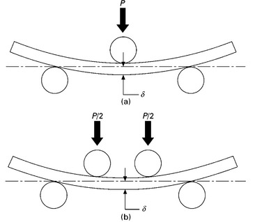
The flexure test measures the mechanical properties of materials when subjected to bending load. A flat rectangular specimen is loaded at three or four points, as shown in Fig. 5.14. The load causes the specimen to flex, thus inducing a compressive strain on the concave side, tensile strain on the convex side, and shear along the mid-plane. The separation distance between the support points must be sufficiently large to avoid the generation of high shear stress. This is achieved by setting the ratio of the length of the outer span L to the specimen height h to 16:1 or greater. This ensures failure occurs by tension or compression failure at the surface, rather than by shear.

5.14 Flexure test performed under (a) three-point and (b) four-point bending.
During the flexure test, the reaction of the specimen to increasing force is measured to calculate the bending stress–strain curve. The flexure strain is related to the vertical displacement of the specimen (δ) by:
where L is the support span between the two outer points, and w and h are the width and height of the specimen, respectively. The flexure stress is determined by:
Flexure testing can determine several important mechanical properties, including the flexural modulus, yield stress and breaking stress. Flexure tests are often done on brittle materials and fibre–polymer composites, but only rarely on ductile materials such as metals.
Leave a Reply