Figure 3.2 shows the main structural components in a modern military aircraft, which are the fuselage, wings, empennage, landing gear and control surfaces such as flaps, elevators and ailerons. Aircraft structures must be lightweight and structurally efficient, and this is achieved by the combination of optimised design and high-performance materials. Many major aircraft sections, including the fuselage, wing and empennage, are shell-like structures known as monocoque or semimonocoque (Fig. 3.3). A monocoque structure is an unreinforced shell that must be thick to avoid buckling under an applied load. A semimonocoque structure consists of a thin shell supported by longitudinal stiffening members and transverse frames to resist bending, compression and torsion loads without buckling. Both types of structure are used in aircraft, although semimonocoque construction is used more widely than monocoque.
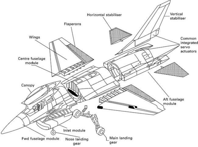
3.2 Main structural components of a modern military aircraft.
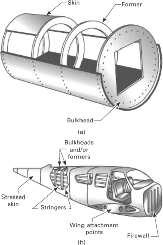
3.3 Examples of (a) monocoque and (b) semimonocoque fuselage structures.
An aircraft structure is required to support one or two types of loads: ground loads and flight loads. Grounds loads are, as the name implies, encountered by aircraft during movement on the ground, such as landing, taxiing and hoisting loads. Flight loads (sometimes called ‘air loads’) are imposed on aircraft during flight. Aircraft designed for a special role may be subjected to additional loads unique to their operation. For example, carrier-borne aircraft are subject to catapult take-off and arrested landing loads, as well as high vertical descent loads on landing. Ground and flight loads can be further divided into surface loads and body loads. Surface loads such as aerodynamic and hydrostatic pressures act over the skin of an aircraft. Aerodynamic pressures acting on the underside of aircraft wings or helicopter rotor blades are examples of surface loads. Body forces act over the volume of the structure and are produced by gravitational forces and inertia loads. For example, the force applied on the undercarriage during landing is a body force. Forces exerted on the aircraft wing-box from the wings and fuselage are another instance of body loads. The surface and body loads applied to aircraft structures are resolved in the structure as tension, compression, bending, shear, torsion or a combination of these load types.
The loads exerted on the airframe, which includes the fuselage, wings and empennage, are carried by both the skins and internal frames which includes stringers, spars, circumferential frames, pressure bulkheads and various other reinforcing members. The internal structure of an airframe is complex, but is designed with an optimum configuration of load-bearing members to provide high structural performance combined with light weight (Fig. 3.4). A critical aspect in the optimum design of an airframe is the selection of materials for each structural detail that possess the required combination of physical, mechanical and durability properties.
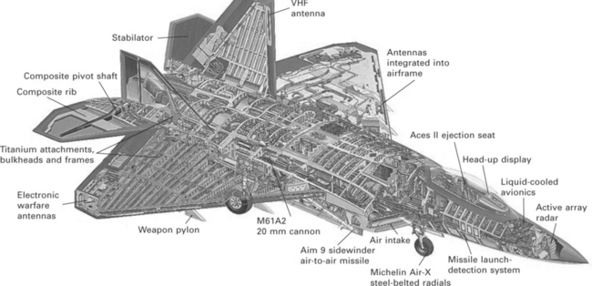
3.4 Internal structural design of a modern aircraft.
Fuselage
The fuselage is a long cylindrical shell, closed at its ends, which carries the internal payload. The dominant type of fuselage structure is semimonocoque construction. These structures provide better strength-to-weight ratios for the central portion of the body of an airplane than monocoque construction. A semimonocoque fuselage consists of a thin shell stiffened in the longitudinal direction with stringers and longerons and supported in the radial direction using transverse frames or rings (Fig. 3.5). The strength of a semimonocoque fuselage depends mainly on the longitudinal stringers (longerons), frames and pressure bulkhead. The skin carries the cabin pressure (tension) and shear loads, the longitudinal stringers carry the longitudinal tension and compression loads, and circumferential frames maintain the fuselage shape and redistribute loads into the airframe.
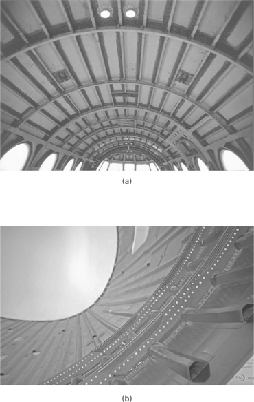
3.5 Semimonocoque fuselage structures made using (a) aluminium alloys and (b) carbon–epoxy composite. ((a) reproduced with permission from R. Wilkinson, Aircraft structures and systems, Longman)
The primary loads on the fuselage are concentrated around the wing-box, wing connections, landing gear and payload. During flight the upward loading of wings coupled with the tailplane loads usually generates a bending stress along the fuselage. The lower part of the fuselage experiences a compressive stress whereas the upper fuselage (called the crown) is subject to tension. Shear loads are generated along the sides of the fuselage and torsion loads when the aircraft rolls and turns. Pressurisation of the cabin for high-attitude flying exerts an internal tensile (hoop) stress on the fuselage.
Figure 3.6 shows the property requirements for fuselage materials. Important properties for fuselage materials are stiffness, strength, fatigue resistance, corrosion resistance, and fracture toughness. Although all of these properties are important, fracture toughness is often the limiting design consideration in aluminium fuselages. Fuselage materials need good resistance against fatigue cracking owing to pressurisation and depressurisation of the fuselage with every flight. Aluminium alloy has been the most common fuselage material over the past eighty years, although carbon fibre-epoxy composite is regularly used in the fuselage of military fighters and increasingly in large passenger aircraft. For example, the Boeing 787 fuselage is constructed using carbon-epoxy composite. GLARE, which is a metallic laminate material, and carbon-epoxy are used extensively in the fuselage of the Airbus 380.
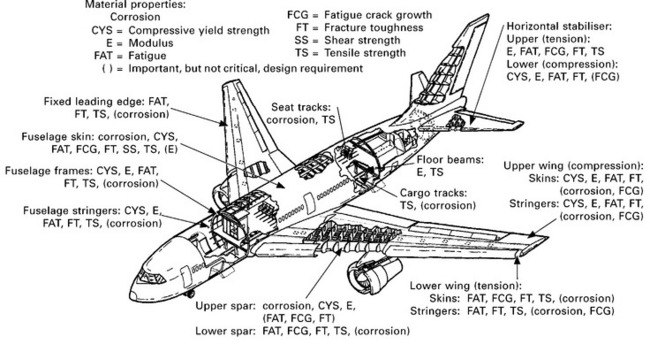
3.6 Material property requirements for the main aircraft structures. reproduced with permission from J. T. Staley and D. J. Lege, ‘Advances in aluminium alloy products for structural applications in transportation’, Journal de Physique IV, 3 (1993), 179–190)
Wings
The main function of the wing is to pick up air loads to maintain flight and to transmit these loads to the fuselage (via the wing-box and wing connections). Additional loads on the wing are internal fuel pressure, landing gear forces, wing leading and trailing edge loads, and the engine weight (when wing mounted). The wing loading, which is simply the total flying weight divided by the wing area, varies between aircraft types. For example, the maximum wing loading with full take-off weight for a Piper Arrow is about 80 kg m− 2, Airbus 380 is 700 kg m− 2, Boeing 747 is 750 kg m− 2 and Tornado is 1100 kg m− 2. The wings account for 20–25% of the structural weight of an aircraft and, therefore, it is imperative that lightweight materials are used.
Wings are constructed of thin skins supported on the inside by stringers and spars, and are designed to carry bending, shear and torsion loads. The bending load is a combination of tension and compression forces. When the aircraft is on the ground the wings hang down under their own weight, the weight of fuel stored inside them, and the weight of engines if these are wing-mounted. This creates a tension load along the upper wing surface and a compression load on the lower surface. During flight when the loads are much higher, however, the bending loads are reversed. The wing bends upwards in flight to support the weight of the aircraft, and this generates compression in the upper surface and tension in the lower surface as shown in Fig. 3.7.
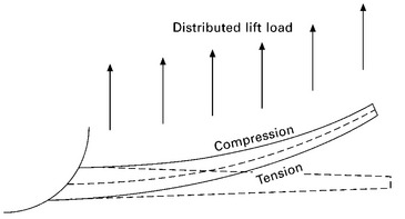
3.7 Bending action of an aircraft wing during flight.
The property requirements for the materials used in the wing are given in Fig. 3.6. The materials used in wings must have high stiffness and strength to withstand the bending, shear and torsion loads. Other requirements include light weight, damage resistance against bird strike at the leading edges, and durability. An important requirement is high fatigue strength to resist damage and failure from fluctuating loads owing to flight manoeuvring, turbulence and wind gusts. In military combat aircraft the fluctuations in stress are generally higher than commercial aircraft owing to the need for frequent and fast manoeuvring. These fluctuating loads can induce fatigue damage. Fatigue of metal structures is favoured by fluctuating tensile loads whereas fatigue damage does not occur in compression, and therefore the lower (tension) and upper (compression) wing surfaces have different material requirements. For this reason, several materials are used in a single aircraft wing. For example, subsonic aircraft wings have traditionally been made using two types of aluminium alloys: high compressive strength alloy (such as 2024 Al) for the upper wing surface and high tensile strength alloy (e.g. 7075 Al) for the lower surface. Wings are increasingly being constructed using carbon–epoxy composite materials owing to their combination of high strength and fatigue resistance. Wings can be constructed using both metals and composites, such as the skins consisting of carbon–epoxy composite and the stringers and spars made of high-strength aluminium or titanium alloys.
Supporting structures on the wing such as attachments to the fuselage and landing gear are designed for strength, fatigue and fracture toughness. The wing-box and wing connections are more highly loaded than the wing itself and therefore are made of materials with higher strength, fatigue life and fracture toughness than the aluminium alloys used in the main wing section. The wing-box and wing connections in modern aircraft are usually constructed with titanium alloy or carbon–epoxy composite.
The wings hold control surfaces such as flaps, elevators and ailerons. Flaps control the amount of lift needed for take-off and landing; elevators control the pitch; and ailerons control the roll. Control surfaces are, in the main, lightly loaded and do not require high strength. However, they require impact resistance against bird strike and flying debris kicked up from the runway by the aircraft during take-off and landing. Control surfaces are usually constructed with thin skins supported by internal stiffeners or foam/cellular materials.
Empennage and control surfaces
The empennage is the whole tail unit at the extreme rear of the fuselage and it provides the stability and directional control of the aircraft (Fig. 3.8). Structurally, the empennage consists of the entire tail assembly, including the vertical stabiliser, horizontal stabilisers, rudder, elevators, and the rear section of the fuselage to which they are attached. The stabilisers are fixed wing sections which provide stability for the aircraft to keep it flying straight. The horizontal stabiliser prevents the up-and-down, or pitching, motion of the aircraft nose. Important material properties are elastic modulus, strength, fatigue resistance and fracture toughness. The rudder is used to control yaw, which is the side-to-side movement of the aircraft nose. The elevator is the small moving section at the rear of the horizontal stabiliser used to generate and control the pitching motion. The loads on the rudder and elevator are smaller than those acting on the vertical and horizontal stabilisers, although properties such as stiffness, strength and toughness are still critically important.
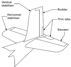
3.8 Typical empennage lay-out.
The empennage in large aircraft also houses the auxiliary power unit (APU). An APU is a relatively small gas turbine used to generate power to start the main turbine engines and to provide electricity, hydraulic pressure and air conditioning while the aircraft is on the ground. The empennage in older versions of passenger aircraft also houses the main turbine engine. Aluminium alloy is the most common structural material used in the empennage and control surfaces, although fibre-polymer composites are increasingly being used for weight saving.
Landing gear
The landing gear, which is also called the undercarriage, is a complex system consisting of structural members, hydraulics, energy absorption components, brakes, wheels and tyres (Fig. 3.9). Additional components attached to and functioning with the landing gear may include steering devices and retracting mechanisms. Of the many components, it is the structural members that support the heavy landing loads and stop the landing gear from collapsing under the aircraft weight. The materials must be strong enough to support heavy take-off weight when an aircraft has a full load of fuel and the high impact loads on landing. Landing gear materials must therefore have high static strength, good fracture toughness and fatigue strength, and the most commonly used materials are high-strength steel and titanium alloy.
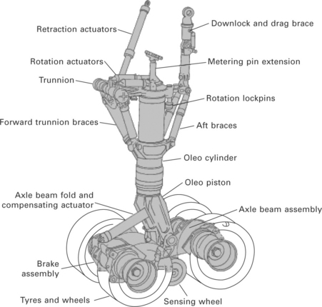
3.9 Main-wheel bogie. (from S. Pace, North American Valkyrie XB-70A, Aero Series vol. 30, Tab Books, 1984)
Jet engines
The materials used in jet engines are subjected to the most arduous working temperatures in an aircraft. Jet engines are gas turbines that compress air to high pressure and this air is then heated to extreme temperature by burning fuel to produce hot, high-pressure gases which are expelled from the engine exhaust thus propelling the aircraft forward. The engine materials must perform for long periods under high temperatures and stresses while exposed to hot corrosive and oxidising gases generated by the burning fuel. Jet engine materials must possess high tensile strength, toughness, fatigue strength and creep resistance together with excellent resistance against corrosion and oxidation at high temperature.
Most conventional materials cannot survive the severe conditions in the hottest section of jet engines, the combustion chamber, where temperatures reach ~ 1500 °C (2760 °F). A group of materials called superalloys, which includes nickel-based, cobalt-based and iron-nickel alloys, are used in the hot sections of jet engines. Ceramic materials with high heat insulating properties are coated on the superalloys to provide protection against the extreme heat. Titanium alloys and composites, which are lighter than superalloys but have lower temperature capacity, are used in cooler parts of the engine, such as the inlet.
Leave a Reply