Groundwater and seepage control needs a most significant consideration in the construction of buildings. Groundwater can be controlled depending on the geological conditions and characteristics of the soil. In such a situation, groundwater can be controlled by adopting one or more types of de-watering systems or drain appropriate to the size and depth of excavation.
Following are some of the de-watering methods:
- Pumping Methods
- From open sumps and ditches
- From well-point systems
- From deep-well drainage
- From vacuum de-watering.
- Electro-osmosis
- Elimination or reduction of ground water by
- Cement grouting
- Displacement grouting
- Chemical consolidation
- Freezing
Pumping and electro-osmosis methods are discussed below. For other methods, reference may be made to Purushothama Raj (2013).
1. Pumping Methods
(i) Open Sumps and Ditches
The essential feature of the method is a sump below the ground level of the excavation at one or more corners or sides (Fig. 32.9).
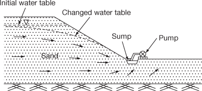
Figure 32.9 De-watering through sumps
In fairly permeable soils the head is low and flow does not emerge through the excavation slopes. In such cases pumping out can be done by collecting the seepage in the sump and pumping out.
In case of excavation in clays the groundwater seeps from fissures and can readily pumped out from sumps. Salty soils generally pose problems. In rocks ground water discharges in the form of sprays or weeps from fissures. Therefore no instability problem in rocks except the water seeps through a weak or shattered rock. The discharges can be collected in an open sump and pumped out.
In order to provide the required number and capacities of pumps the quantity of water to be pumped should be known. This is calculated from Dupit’s formula.
(ii) Well-Point Systems
Filter wells or well-points are small well screens of sizes 50–80 mm in diameter and 0.3–1 m length. Well-points are made of brass or stainless steel screens and of closed ends or self-jetting types. When well-points are required to remain in the ground for a long period disposable plastic well-points are used. The plastic well-points are of nylon mesh screens surrounded by flexible plastic riser pipes. Water drawn through the screen enters the space between the gauze and the outside of the riser pipe through holes drilled in the bottom of the pipe and then reaches the surface. The well-points are installed by jetting them into the ground. A typical layout of a single stage well-point is shown in Fig. 32.10.
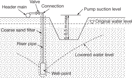
Figure 32.10 Single stage well-point installation
A well-point system, in general, comprises of well-points which are attached to riser pipes, which extend a short distance above the surface of the ground, where they are connected to a large pipe called header. The header pipe is connected to the suction of a centrifugal pump. A well-point system may include a few or several hundred well-points (generally 50–60 well points) all connected to one or more headers and pumps.
Well-point systems are very effective in solving subsurface water problem on construction sites. These systems are used to provide dry work areas below the water table for the following works:
- Foundation work including buildings, bridges, dams and dry dock.
- Trench work including buildings, bridges, dams and dry dock.
- Tunnel work such as subway construction.
(iii) Deep-well Drainage
If the soil formation is such that it is pervious with depth, large diameter deep-wells are suitable for lowering the ground water table. An advantage of the system is that it can be installed outside the zone of construction operation and drainage is effected to the depth of excavation. Deep-wells may be combined with the well-point system on certain occasions for lowering the ground water table (Fig. 32.11).
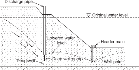
Figure 32.11 Deep-well de-watering
Presence of artesian pressure in some field conditions may be relieved by deep-wells. The cost of installation of deep-well is high. Thus it is preferred in jobs which have a long construction period.
The deep wells are installed by sinking a cased borehole having a diameter of about 300 mm larger than the well casing. The diameter of the latter depends on the size of the submersible pumps. The inner well casing is inserted after the completion of the bore hole.
A perforated screen is provided over the lengths where de-watering of the soil is required. Graded filters of gravel are provided between the well casing and the outer borehole casing over the length to be de-watered. The outer casing is withdrawn in stages as the filter material is placed. The space above the screen is backfilled with any available material. The details of such a deep well are shown in Fig. 32.12. The spacing of deep well vary from 10 to 100 m depending on the field condition.
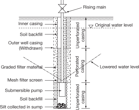
Figure 32.12 Details of deep-well installation
(iv) Vacuum De-watering System
Gravity methods explained so far are not very effective in fine-grained soils. Such soils can be stabilised by means of a vacuum well or well-point system. A vacuum de-watering system primarily consists of well or well-points with the screen and riser pipes.
A stabilising fine soil such as bentonite or impervious soil seal is provided at the remaining portion of the hole. By creating and maintaining a vacuum in the well screen and the sand filter, the flow towards the well is increased. A closer spacing is required (Fig. 32.13) for proper de-watering.
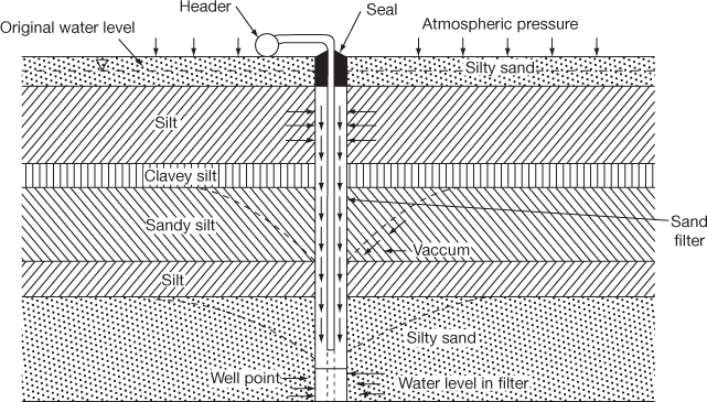
Figure 32.13 Vacuum de-watering system
2. De-watering by Electro-osmosis
This is also a method applicable for fine-grained soils. This is not a general pumping method but collecting the water through some process to a well and pumping out.
If the vacuum well-point or well-point system is ineffective, application of an electrical gradient may be made. In a fine-grained soil stratum, when a direct electric current is passed through a saturated soil stratum, water moves towards the cathode. If the water is removed at the cathode, the soil decreases in volume resulting in increased shear strength. This process is called de-watering by electro-osmosis.
The general layout of the electrode is based on the purpose for which they are intended. Electrode arrangement for sheeted excavation is shown in Fig. 32.14.
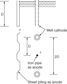
Figure 32.14 Electrode arrangement for sheeted excavation
Sheet piles of any shape and old pipes of 25–50 mm diameter can be made as anodes. Since the anodes corrode considerably in the course of a few weeks of electro-osmotic treatment, they should be replaced as soon as the current drops to less than 30% of the initial consumption. For cathode perforated tubes are used and the cathode wells are connected to a pumping system.
Electro-osmotic method is used only when other methods fail as the cost of installation and maintenance are very high.
Leave a Reply