After building the Temperature Indicator circuit and checking for wiring errors, it is time to upload the sketch. Example 20-1 sends analog information to the Arduino IDE (integrated development environment) Serial Monitor, and displays a series of numbers based on the thermistor’s change in resistance. It uses the same serial communication technique used in to talk with the Processing programming language. Here are the steps you’ll need to follow:
- Attach the Arduino microcontroller to your computer using a USB cable.
- Open the Arduino software and type Example 20-1 into the software’s text editor.
- Upload the sketch to the Arduino microcontroller.
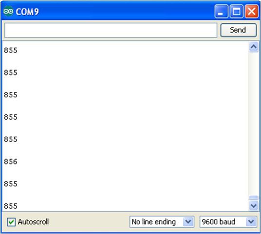
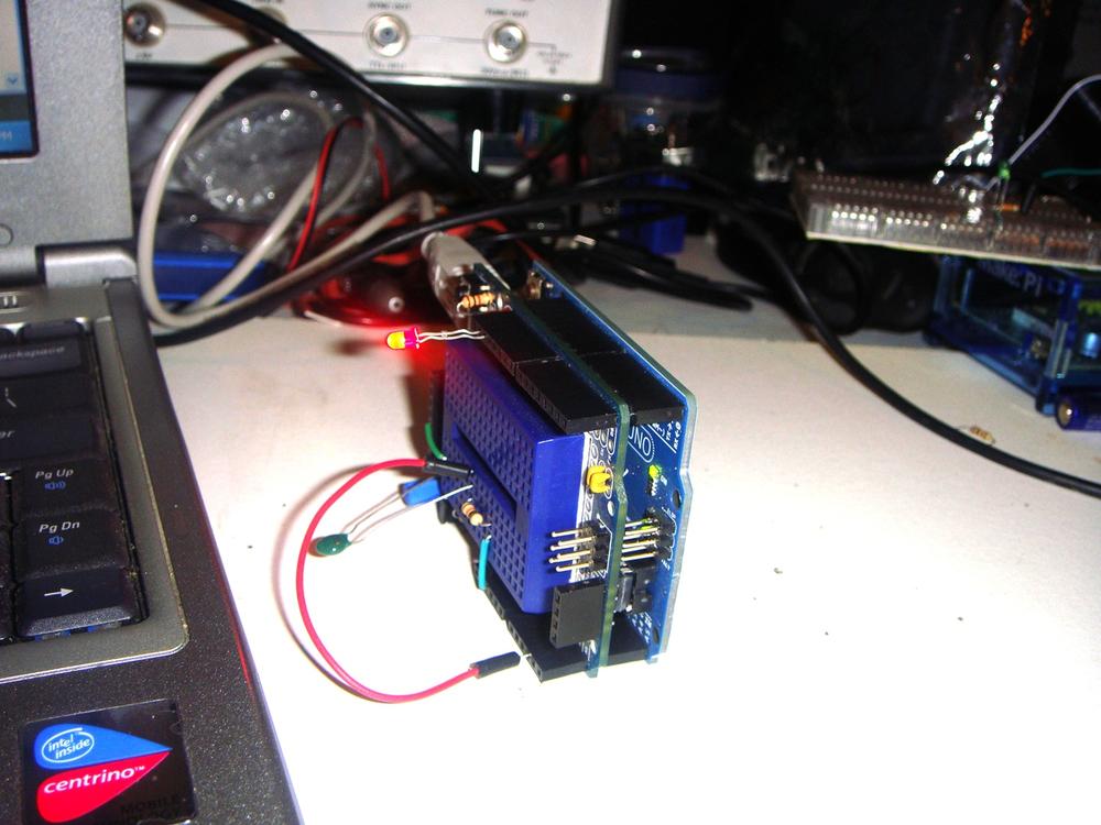
With the Temperature Indicator sketch uploaded to the Arduino microcontroller, the Serial Monitor will display decimal numbers as shown in Figure 20-3. If you touch the thermistor—making it hotter with your own body heat—the Serial Monitor numbers will change. Also, if you add an external LED between pins D13 and GND, you’ll have a visual indicator of when the thermistor’s temperature has exceeded the threshold value programmed in the sketch. Figure 20-4 shows the Temperature Indicator’s LED in operation.The Temperature Indicator is not an actual electronic thermometer but a device that can sense a certain heat level and respond to it by turning on an LED. The temperature units of Fahrenheit or Celsius are not displayed, thereby removing the concern about the thermistor’s temperature resolution so the focus is on the device’s actual operating performance.

Figure 20-3. Decimal numbers being displayed on the Arduino Serial Monitor

Figure 20-4. Temperature Indicator detecting heat from a notebook computer.
TECH NOTE
The thermistor is used in electronic thermometers to measure temperature.
Example 20-1. The Temperature Indicator sketch
/*
*  Temperature_Indicator
*
*  Reads an analog input from the input pin and sends the value
*  followed by a line break over the serial port. Data can be viewed
*  using the Serial Monitor.
*
*  This file is part of the Arduino meets Processing Project:
*  For more information visit http://www.arduino.cc.
*
*  created 2005 ap_ReadAnalog by Melvin Ochsmann for Malmo University
*
*  10 June 2013
*  modified by Don Wilcher
*
*/

// variables for input pin and control LED
  int analogInput = 3;
  int LEDpin = 13;

// variable to store the value
  int value = 0;

// a threshold to decide when the LED turns on
  int threshold = 800;

void setup(){

// declaration of pin modes
  pinMode(analogInput, INPUT);
  pinMode(LEDpin, OUTPUT);

// begin sending over serial port
  Serial.begin(9600);
}

void loop(){
// read the value on analog input
  value = analogRead(analogInput);

// if value greater than threshold turn on LED
if (value < threshold) digitalWrite(LEDpin, HIGH);
else digitalWrite(LEDpin, LOW);

// print out value over the serial port
  Serial.println(value);

// and a signal that serves as separator between two values
  Serial.write(10);

// wait for a bit to not overload the port
  delay(100);
}
Leave a Reply