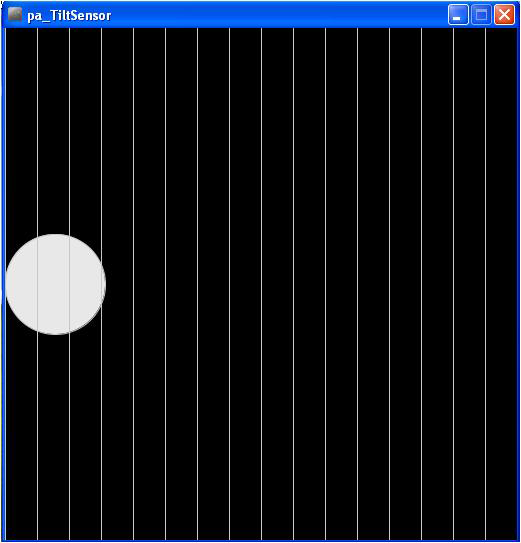
With the Arduino attached to a Processing sketch running on your computer, the digital information (L’s and H’s) from the Arduino can be changed to a horizontally moving white circle based on the orientation of the tilt switch, as shown in Figure 18-5 and Example 18-2.
TECH NOTE
Check out the Processing sketch listings for Arduino projects.
Example 18-2. The pa_Tilt Processing sketch
/*
*  pa_Tilt
*
*  Reads the values which represent the state of a Tilt switch
*  from the serial port and draws white-filled circle with vertical lines.
*  created 2005 by Melvin Ochsmann for Malmo University
*
*/

import processing.serial.*;

  DisplayItems di;

  int xWidth = 512;
  int yHeight = 512;
  int fr = 24;

  boolean bck = true;
  boolean grid = true;
  boolean g_vert = true;
  boolean g_horiz = false;
  boolean g_values = false;
  boolean output = true;

  Serial port;

  // The "2" corresponds to the 3rd port (counting from 0) on the Serial
  // Port list dropdown. You might need to change the 2 to something else.
  String portname = Serial.list()[2];
  int baudrate = 9600;
  int value = 0;
  boolean tilted = true;
  float a = 0;
  int speed = 5; // how many pixels that the circle will move per frame

void keyPressed(){

  if (key == 'B' || key == 'B') bck=!bck;
  if (key == 'G' || key == 'G') grid=!grid;
  if (key == 'V' || key == 'V') g_values=!g_values;
  if (key == 'O' || key == 'O') output=!output;
}

void setup(){

      size(xWidth, yHeight);
      frameRate(fr);

      di = new DisplayItems();

      port = new Serial(this, portname, baudrate);
      println(port);
}
// Method moves the circle from one side to another,
// keeping within the frame
void moveCircle(){

  if(tilted) {
      background(0);

      a = a + speed;
      if (a > (width-50)) {
        a = (width-50);
      }
      ellipse(a, (width/2), 100,100);

  }else{
      background(0);

      a = a - speed;
      if (a < 50) {
        a = 50;
      }
      ellipse(a, (width/2), 100,100);

    }
  }

void serialEvent(int serial){
        if(serial=='H') {
             tilted = true;
              if(output) println("High");

        }else {
             tilted = false;
                if(output) println("Low");
         }
}

void draw(){

  while(port.available() > 0){
        value = port.read();
        serialEvent(value);
    }

    di.drawBack();

    moveCircle();

    di.drawItems();

}
Figure 18-5. An interactive (moving) white-filled circle created in Processing
TECH NOTE
There are a couple of Easter eggs embedded in the pa_Tilt Processing sketch that will allow you to change the appearance of the display. Good Hunting!
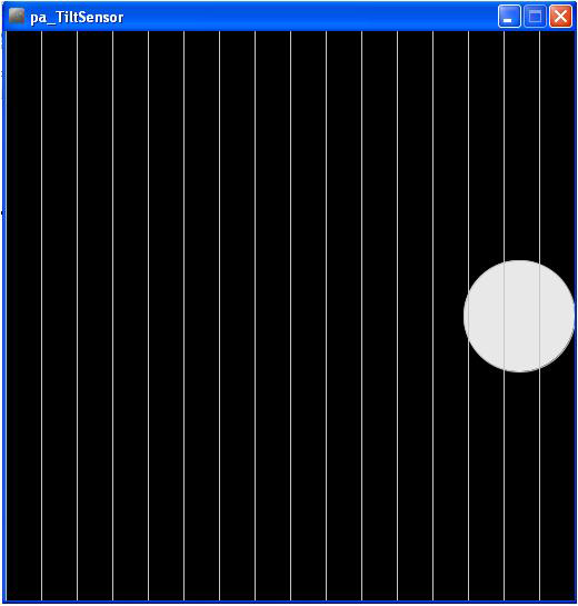
Next, open a new tab in the Processing IDE and add Example 18-3 . After typing the sketch, click the play button. Your computer screen should show something very similar to the image shown in Figure 18-5. Rotate the tilt switch and watch the white circle move across your computer screen, as shown in Figure 18-6.
Example 18-3. The DisplayItems Processing sketch
/*
*  DisplayItems
*
*  This class draws background color, grid and value scale
*  according to the boolean variables in the pa_file.
*
*  This file is part of the Arduino meets Processing Project.
*  For more information visit http://www.arduino.cc.
*
*  created 2005 by Melvin Ochsmann for Malmo University
*
*/

class DisplayItems{

// variables of DisplayItems object
PFont font;
int gridsize;
int fontsize = 10;
String fontname = "Monaco-14.vlw";
String empty="";
int i;

// constructor sets font and fontsize
DisplayItems(){
  font = loadFont(fontname);
  gridsize = (width/2)/16+(height/2)/16;
  if(gridsize > 20) fontsize = 14;
  if(gridsize > 48) fontsize = 22;
  textFont(font, fontsize);
}

// draws background
void drawBack(){
       background( (bck) ? (0) : (255)  );
}

// draws grid and value scale
void drawItems(){
  if(grid){  stroke( (bck) ? (200) : (64) );
             fill((bck) ? (232) : (32) );

  // vertical lines
  if(g_vert){
    for (i=0; i < width; i+=gridsize){
    line(i, 0, i, height);
    textAlign(LEFT);
    if (g_values &&
        i%(2*gridsize)==0 &&
        i < (width-(width/10)))
      text( empty+i, (i+fontsize/4), 0+fontsize);
  }}

  // horizontal lines
  if(g_horiz){
    for (int i=0; i < height; i+=gridsize){
    line(0, i, width, i);
    textAlign(LEFT);
    if (g_values &&
        i%(2*gridsize)==0)
      text( empty+(height-i), 0+(fontsize/4), i-(fontsize/4));
    }}
  }
 }
}// end class Display
Figure 18-6. The Terrific Tilt Switch in action: the white circle has moved to the right side of the screen
TECH NOTE
A class defines the look and operation of software objects.
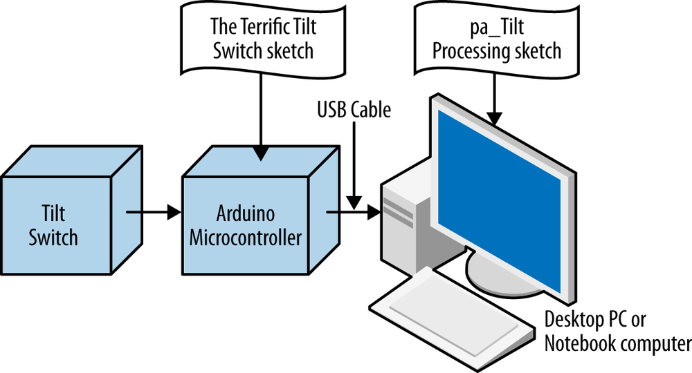
The block diagram in Figure 18-7 shows the electronic component blocks and the data flow for the Terrific Tilt Switch. A Fritzing electronic circuit schematic diagram of the Terrific Tilt Switch is shown in Figure 18-8.

Figure 18-7. The Terrific Tilt Switch block diagram
Leave a Reply