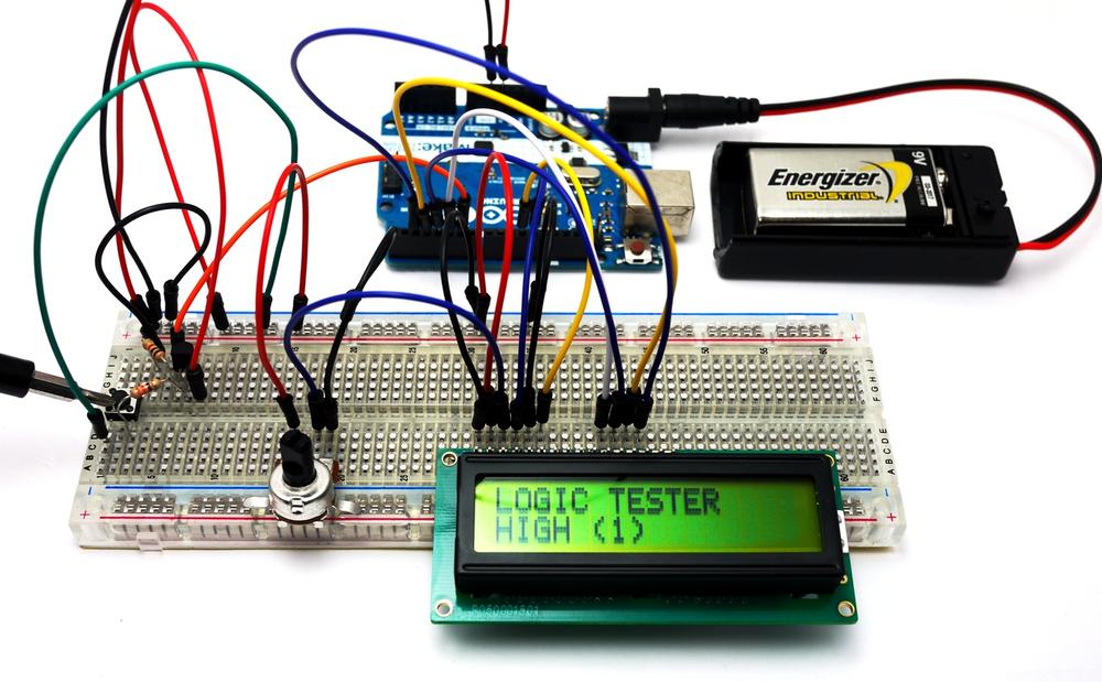
With the Logic Tester built, it’s time to upload the sketch. Example 16-1 operates an LCD using a pushbutton switch, a transistor, and two fixed resistors. Here are the steps you’ll need to follow:
- Attach the Arduino to your computer using a USB cable.
- Open the Arduino software and type Example 16-1 into the software’s text editor.
- Upload the sketch to the Arduino.
Once the Logic Tester sketch has been uploaded to the Arduino, the LCD will display a message, as shown in Figure 16-1. Take the long jumper wire (test probe) from the pushbutton switch and attach it to the +5V source of the Arduino (for reference, see Figure 16-2). Press the pushbutton switch and the LCD will display “HIGH (1)” for the +5V source, as shown in Figure 16-3. Impress the local Makerspace by testing Arduino and digital electronic circuits with your Logic Tester!
Example 16-1. The Logic Tester sketch
/*
  Logic Tester
  LCD displays "HIGH (1)" when digital circuit signal is +5V. A "LOW (0)"
  is displayed when digital circuit signal is OV.

  27 April 2013
  Don Wilcher

 */

// include the LCD library code:
#include <LiquidCrystal.h>

// set up pins on Arduino for LCD and transistor lead:
LiquidCrystal lcd(12,11,5,4,3,2);
int xistorPin = 6;
int digitalStatus = 0;      // variable for reading the digital circuit state


// initialize the transistor pin as an input and set up the LCD's number
// of columns and rows:
void setup() {
  lcd.begin(16,2);
  lcd.setCursor(0,0);
  lcd.print("LOGIC TESTER");
  pinMode(xistorPin, INPUT);

}


void loop() {
  // check if digital signal is HIGH or LOW:
digitalStatus = digitalRead(xistorPin);
if (digitalStatus == HIGH) {
  // if digital circuit signal is +5V, display HIGH (1):
  lcd.setCursor(0,1);
  lcd.print("HIGH (1) ");   // display HIGH (1)
}
else {
  // if digital circuit signal is 0V, display LOW (0):
  lcd.setCursor(0,1);
  lcd.print(" LOW (0) ");
 }
}
Figure 16-3. The Logic Tester testing the Arduino’s +5V source
TECH NOTE
An electrical tester used to check digital circuits is called a logic probe.
Leave a Reply