With the Logic Tester built, it’s time to upload the sketch. As shown in Example 15-1, the sketch operates an RGB LED using a pushbutton switch and two fixed resistors. Here are the steps you’ll need to follow:
- Attach the Arduino to your computer using a USB cable.
- Open the Arduino software and type Example 15-1 into the software’s text editor.
- Upload the sketch to the Arduino.
Once the Logic Tester sketch has been uploaded to the Arduino microcontroller, the RGB’s red LED will be on, as shown in Figure 15-1. Attaching the long test wire to the +5VDC source on the MakerShield and pressing the pushbutton switch will allow the RGB green LED to turn on, as shown in Figure 15-3.
Example 15-1. The Logic Tester sketch
/*
  Logic Tester with RGB LED

  Turns on the green LED when a logic "1" (+5V) signal is detected. The
  red LED will turn on at logic "0" (0V) signal.  Also, when powering
  up the Arduino the red LED is on.

  4 May 2013
  Don Wilcher

 */

// RG pins wired to the Arduino microcontroller
// give them names:
int redled = 9;
int grnled = 10;
int probein = 8;
int probeStatus = 0;

// the setup routine runs once when you press reset:
void setup() {
 // initialize the digital pins as outputs:
  pinMode(redled, OUTPUT);
  pinMode(grnled, OUTPUT);
  pinMode(probein, INPUT);
  // turn RGB outputs off:
  digitalWrite(redled, HIGH);
  digitalWrite(grnled, HIGH);

}

// the loop routine runs over and over again forever:
void loop() {
// read the status of the test probe value:
probeStatus = digitalRead(probein);

if (probeStatus == HIGH) { // check if the test probe value is HIGH

  digitalWrite(redled, HIGH);       // turn the red LED off (HIGH is off)
  digitalWrite(grnled, LOW);        // turn the green LED on (LOW is on)
 }
else {

   digitalWrite(redled, LOW);       // turn the red LED on
   digitalWrite(grnled, HIGH);      // turn the green LED off

   }
}
TECH NOTE
HIGH is equivalent to binary 1 and LOW is equivalent to binary 0.
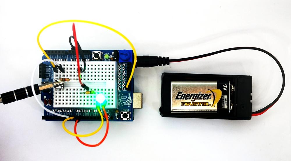
Figure 15-3. The Logic Tester checking +5VDC on MakerShield
Leave a Reply