It’s time to upload the Ohmmeter sketch to the Arduino. Example 13-1 reads the resistance of R2, and reports the result through the serial display. Here are the steps you’ll need to take:
- Attach the Arduino to your computer using a USB cable.
- Open the Arduino software and type Example 13-1 into the software’s text editor.
- Upload the sketch to the Arduino.
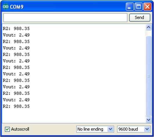
Once the Ohmmeter sketch has been uploaded to the Arduino, place the unknown resistor (shown as R2 on the Frizting diagram) you want to test in series with the reference resistor R1 (1KΩ) connected to GND. The voltage across the R2 resistor and its resistance value will be displayed on the Serial Monitor. Figure 13-3 shows the output voltage (Vout) and the measured resistance of a 1KΩ resistor (R2) being displayed on the Serial Monitor.

Figure 13-3. R2 and Vout measured and displayed on the Serial Monitor
Example 13-1. The Arduino Ohmmeter sketch
/*
  Arduino Ohmmeter

 */

// set up pins on Arduino for LED and test lead
int analogPin = 0;     // reads the resistance of R2
int raw = 0;           // variable to store the raw input value
int Vin = 5;           // variable to store the input voltage
float Vout = 0;        // variable to store the output voltage
float R1 = 1000;       // variable to store the R1 value
float R2 = 0;          // variable to store the R2 value
float buffer = 0;      // buffer variable for calculation

void setup()
{
  Serial.begin(9600);             // Set up serial

}

void loop()
{
  raw = analogRead(analogPin);  // reads the input pin
  if(raw)
    {
        buffer = raw * Vin;
        Vout = buffer /1024.0;  // calculates the voltage on the input pin
        buffer = (Vin / Vout) - 1;
        R2 = R1 / buffer;
        Serial.print("Vout: ");
        Serial.println(Vout);           // outputs the information
        Serial.print("R2: ");           //
        Serial.println(R2);             //
        delay(1000);
   }
}
TECH NOTE
The value of R1 is stored using a float variable type in the sketch. Change the value from 1000 (1KΩ) to a higher value when reading higher resistance values.
Leave a Reply