This project demonstrates the power of electronic sensors to detect physical stimuli such as light, sound, and pressure. With a slight modification to the sketch, messages can scroll across a Serial Monitor. The Arduino IDE has a Serial Monitor for displaying the messages produced by the Arduino. You can access the Serial Monitor by following these two steps:
- Move your mouse to the main toolbar of the Arduino IDE and click Tools.
- Move the cursor, highlight “Serial Monitor,” and click it.
The Serial Monitor will be displayed on your computer’s screen. It’s just that easy! The modifications to your sketch to display the messages “Sunrise” and “Sunset” on the Serial Monitor are shown in Example 2-2.
Example 2-2. Sunrise Sunset Detector with Serial Monitor sketch
const int lightsensorPin = 2;  // the number of the light sensor pin
const int redledPin = 12;      // the number of the red LED pin
const int greenledPin13 = 13;  // onboard LED and green LED pin

// variables will change:
int sensorState = 0;      // variable for reading light sensor status


void setup() {
  // initialize the LED pins as outputs:
  pinMode(redledPin, OUTPUT);
  pinMode(greenledPin13, OUTPUT);
  // initialize the light sensor pin as an input:
  pinMode(lightsensorPin, INPUT);
 // initialize serial communications at 9600 bps:
 Serial.begin(9600); // Add code instruction here!
}

void loop(){
  // read the state of the light sensor value:
  sensorState = digitalRead(lightsensorPin);

  // check if the light sensor is activated
  // if it is, the sensorState is HIGH:
  if (sensorState == HIGH) {
    // turn red LED on:
    digitalWrite(redledPin, HIGH);
    // turn off onboard LED and green LED:
    digitalWrite(greenledPin13, LOW);
    // display message
    Serial.println("Sunset\n"); // Add code instruction here!

  }
  else {
    // turn red LED off:
    digitalWrite(redledPin, LOW);
    // turn on onboard LED and green LED;
    digitalWrite(greenledPin13,HIGH);
    // display message
    Serial.println("Sunrise\n"); // Add code instruction here!
  }
}
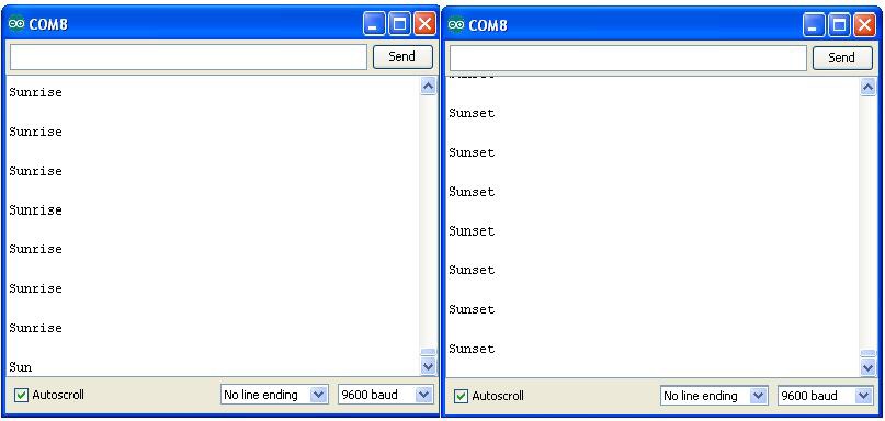
With the modifications made to the original sketch, upload it to the Arduino and open the Serial Monitor. As you wave your hand over the photocell, you see the messages “Sunrise” (no hand over the sensor) and “Sunset” (hand over the sensor) displayed on the Serial Monitor. Figure 2-5 shows the two messages displayed on the Serial Monitor.
Experiment with the location of the Sunrise-Sunset detector to obtain the best circuit response. Enjoy!
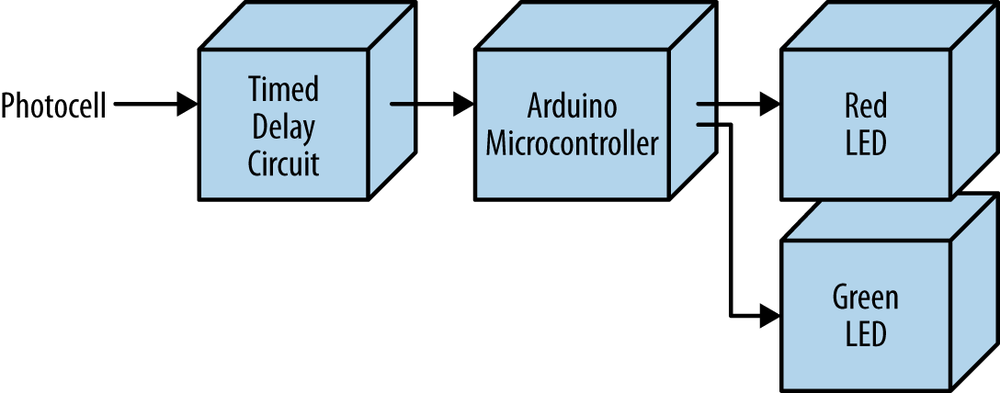
The block diagram in Figure 2-6 shows the electronic component blocks and the electrical signal flow for the Sunrise-Sunset Light Switch. A Fritzing electronic circuit schematic diagram of the switch is shown in Figure 2-7. Electronic circuit schematic diagrams are used by electrical/electronic engineers to design and build cool electronic products for society.

Figure 2-5. Serial Monitor displaying “Sunset” and “Sunrise” messages

Figure 2-6. Sunrise-Sunset Light Switch block diagram
TECH NOTE
Always document your experiments and design changes in a lab notebook in case you develop that million dollar idea!
Leave a Reply