Up Milling and Down Milling: The horizontal milling is divided into two groups: up milling and down milling. If the direction of cutting and feed are opposite to each other, the milling is known as up milling, and if the direction of both are same, the milling is known as down milling as shown in Figure 19.42. In down milling there is tendency of the job being dragged into the cutter, therefore, up milling is safer and is commonly used. However, down milling results in better surface finish and longer tool life. In down milling the chip thickness starts at maximum and decreases to its minimum value at the end of the cut where tooth leaves the work. In up milling the chip thickness starts at zero and increases to its maximum value at the end of the cut where the tooth leaves the work. Cutting forces tend to lift the workpiece up from the table, hence the name up milling.
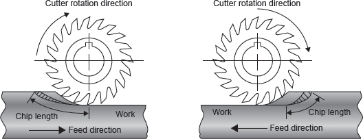
Figure 19.42 Up Milling and Down Milling
Slab Milling: Slab milling, also called peripheral milling or plane milling generates flat surfaces by using the teeth located on the periphery of the cutter body as shown in Figure 19.43. The axis of cutter rotation is parallel to the workpiece surface to be machined. The diameter and width of the cutter depend on the part that is to be slab milled.
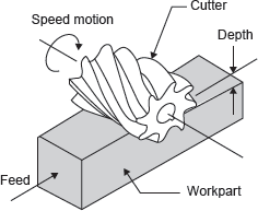
Figure 19.43 Slab Milling
Generally, helical teeth cutter is selected for slab milling. Less force is required; vibration and chatter are reduced; and a better quality of surface finish is produced with a helical tooth cutter than with a straight tooth cutter. This is possible because of the fact that the helical teeth are continuously engaged in comparison with the intermittent cutting action of straight tooth cutter. Milling cutters up to 18 mm wide generally have straight teeth and cutters over 18 mm wide usually have helical teeth. Angle of helix ranges from 45° to 60° or steeper. Straight cutters are used for light duty and helical for heavy duty.
Side Milling: Side milling uses side milling cutters similar to plain milling cutters. However, in addition to teeth around the periphery, other cutters are formed on one or both sides as shown in Figure 19.44. The teeth may be either straight or helical. Most of the cutting is done by the teeth around the periphery.

Figure 19.44 Side Milling
The side cutting teeth cut the side of the workpiece. Side mills are not recommended for milling slots because of their tendency to mill wider.
End Milling: End milling is a process of machining horizontal, vertical, angular, and irregular shaped surfaces. The cutting tool is called an end mill as shown in Figure 19.45. End mills are coarse tooth cutters and made of high speed steel or have carbide inserts. They are subjected to severe torsion and bending stresses in use. These limit the size of cut that can be taken. With a cut equal to the full width of the cutter, the maximum recommended depth of cut in 0.6D, D being the diameter of end mill. If, however, the cutting action is the cleaning up of the edge of a component, with the cut only 10% of the diameter, the depth can be increased to 1.5D.
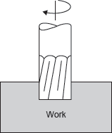
Figure 19.45 End Milling
This process can be used to mill grooves, slots, keyways, and large surfaces. It is also widely used for profile milling in die making.
Face Milling: Face milling is an extension of end milling where the cutter has large diameter with several cutting teeth as shown in Figure 19.46. The cutter diameter is usually 6 in. or more. The teeth are bevelled or rounded at the periphery of the cutter.
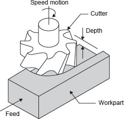
Figure 19.46 Face Milling
Face milling cutters are made of high speed steels, cast alloys, or carbides and are heavy duty cutters. Heavy cuts, coarse feeds, and high cutting speeds are essential. The cutter is mounted on a spindle having an axis of rotation perpendicular to the workpiece surface; face milling is used to produce a flat surface and has a wide variety of applications.
Gang Milling: It is the milling operation which involves the use of a combination of more than two cutters, mounted on a common arbour, for milling a number of flat horizontal and vertical surfaces of a workpiece simultaneously as shown in Figure 19.47. This combination may consist of only side milling cutters or plain milling cutters or both.
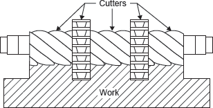
Figure 19.47 Gang Milling
Straddle Milling: It is a milling operation in which a pair of side milling cutters is used for machining two parallel vertical surfaces of a workpiece simultaneously as shown in Figure 19.48.

Figure 19.48 Straddle Milling Cutter
Form Milling: This milling process is employed for machining those surfaces which are of irregular shapes. The cutter used, called a form milling cutter, has the shape of its cutting confirming to the profile of the surface to be produced. Form milling cutter is shown in Figure 19.49.

Figure 19.49 Form Milling Cutters
Profile Milling: It is the operation in which the profile of a template or the shape of the cavity of a master die is duplicated on the work surface. The movement of the cutter is guided by a tracer control unit which carries a contact finger. This finger (stylus) runs in contact with the outline to be duplicated and the tracer mechanism guides the tool movement accordingly.
Leave a Reply