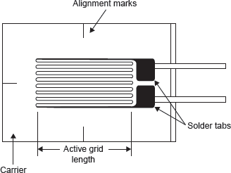
There are several methods of measuring strain; the most common is a strain gauge, a device whose electrical resistance varies in proportion to the amount of strain produced in the device. For example, the piezoresistive strain gauge is a semiconductor device whose resistance varies non-linearly with strain produced. The most widely used gauge is the bonded metallic strain gauge. The metallic strain gauge consists of a very fine wire or more commonly, metallic foil arranged in a grid pattern. The grid pattern maximizes the amount of metallic wire or foil subject to strain in the parallel direction (Figure 18.10).

Figure 18.10 Bonded Metallic Strain Gauge
The cross-sectional area of the grid is minimized to reduce the effect of shear strain and Poisson strain. The grid is bonded to a thin backing, called the carrier, which is attached directly to the test specimen. Therefore, the strain experienced by the test specimen is transferred directly to the strain gauge, which responds with a linear change in electrical resistance. Strain gauges are available commercially with nominal resistance values from 30 to 3,000 Ω, with 120, 350, and 1,000 Ω being the most common values.
It is very important that the strain gauge be properly mounted onto the test specimen so that the strain is accurately transferred from the test specimen, through the adhesive and strain gauge backing, to the foil itself. Manufacturers of strain gauges are the best source of information on proper mounting of strain gauges.
A fundamental parameter of the strain gauge is its sensitivity to strain, expressed quantitatively as the gauge factor (GF). GF is defined as the ratio of fractional change in electrical resistance to the fractional change in length (strain):

The GF for metallic strain gauges is typically around 2.
Leave a Reply