For a great tutorial on how to solder, study the “Adafruit Guide to Excellent Soldering.”
Now, finally, you’re ready to start soldering!
WARNING
Don’t rush. Be careful. Remember to breathe and relax. Double-check the schematic for each connection before you solder it. Inspect your work often for bad solder joints or other mistakes.
Don’t try to make all the connections at once. Do them in small groups, and take a short break between groups. When you come back, double-check what you just did.
Try not to follow my directions blindly. Try to understand what’s being done and make sure you agree with it.
You can remove the screw terminals and the sockets for now so that you can place the shield flat on your work surface to keep the parts in place.
Solder the sockets in place first to keep them from falling out. This will also give you a chance to practice soldering a little.
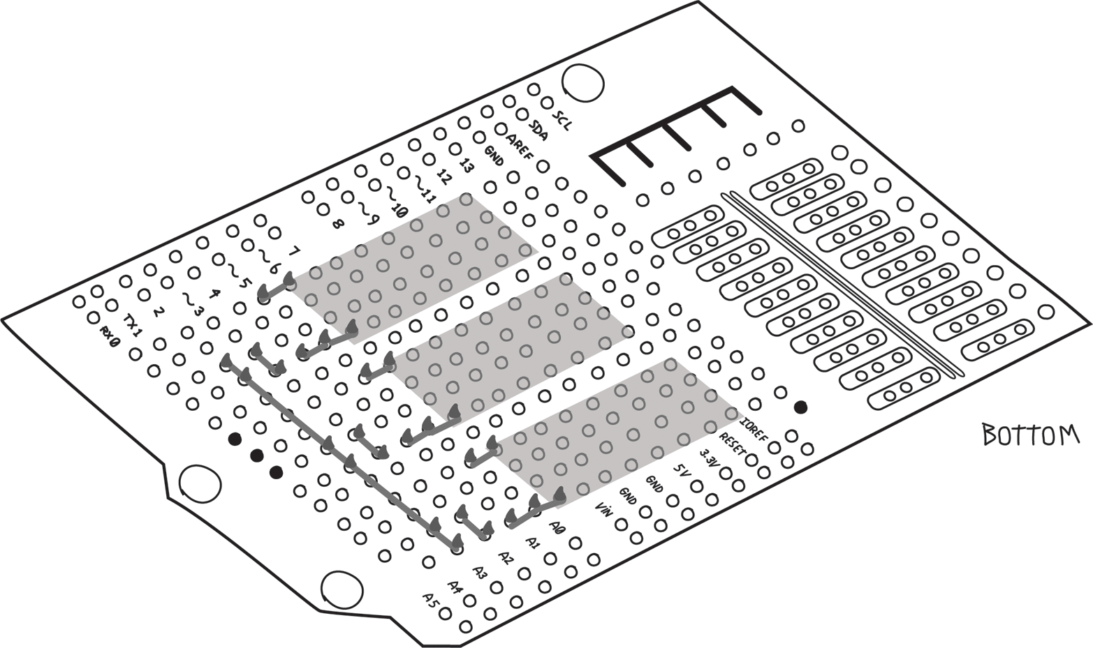
Next come the sets of diode, MOSFET, and resistor. Remember that we wanted to use their leads (on the bottom of the board) to make the connections. Bend them over very flat against the board so that the components are pulled tight against the board, and then over to where you need to make the connection. You don’t need to wrap the lead around the pin; it’s enough that the lead overlaps the pad around the pin. Make sure the solder flows onto all leads that are being connected.
When you’re done soldering a connection, cut any excess leads as close as possible to the solder joint. You don’t want any extra bit poking out that might touch something else later. This is detailed in the “Making a good solder joint” tutorial by Adafruit.
WARNING
When you trim a lead or wire after soldering, make sure you catch the piece you cut off and throw it away, to make sure it does not fall back on your work, where it might touch something it shouldn’t and make a short circuit.
The MOSFET source pins all go to GND, so they chould be connected together. You can use the long leads of the resistors to connect all three together, which will provide a useful GND strip for anything else that needs to be connected to GND. These common strips are often called buses. Note that at this point our GND bus is not yet connected to the Arduino GND. I usually leave that for later so as not to occupy a hole that I later might need, but we have to remember to make this connection at the end.
Figure 8-20 shows the bottom view, with all the leads folded over and soldered in place. The shadowed areas indicate the relay sockets on the top side, and the cones indicate the solder.
Now you can replace the screw terminals. Before you solder them in place, make sure the openings for the wire are facing the right direction, towards the outside of the board! (Another mistake I learned the hard way.) As always, make sure they are flush against the shield. Leave the sockets for later.
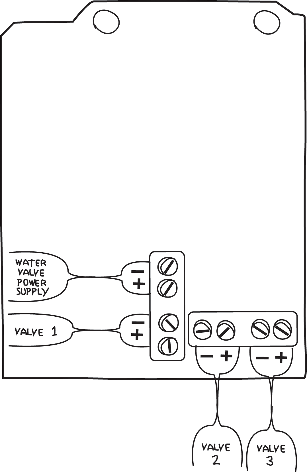
At this point it’s a good idea to decide which screw terminal is what. Document this as shown in Figure 8-21 so that you don’t forget and make the wrong connection later.
Now you can add the indicator LEDs and their associated diodes and resistors. Again, by cleverly placing these components, you can use the component leads to make the connections. Note that this particular Proto Shield has some rows of three connected pins. I used these to help with the connections. Remember that LEDs and diodes are polarized: the anode (longer lead) of each LED goes to the screw terminal, and the anode of each diode goes the cathode of its LED.
It’s important to note that there are two strips (buses) of 5V and GND that we’re not using, so you have to carefully make sure the LED leads are above these and do not touch them. If the LED accidentally touched 5V or GND, this could bring the 24 V from the water valve power supply into Arduino, which would probably damage the Arduino. To be safe, you can cut a piece of electrical tape to the proper size and tape it over the 5V and GND buses. These buses are on the bottom side as well and must be avoided there too.
In Figure 8-22 we’ve shown the components quite high so that you can see where they are all connected, but when you build the circuit, place them as close to the shield as possible, as mentioned earlier. Remember that this illustration is distorted to enlarge certain details, but that the holes used are accurate.
In this and many of the following figures I’ve left off most of the components from previous steps so that you can see more clearly the components and locations of each step.
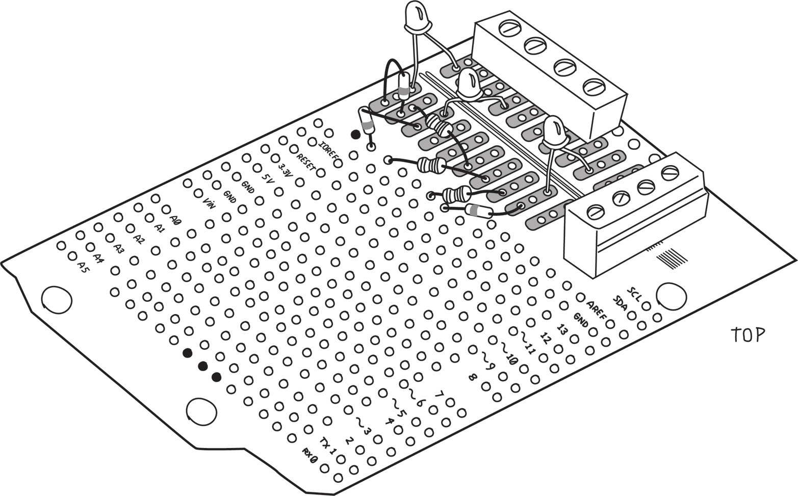
Figure 8-23 shows the bottom view. As before, we’ve used the component leads to make connections to each other and to the screw terminals. It’s a good thing we documented the screw terminals, because we’d get confused now as to which one does what.
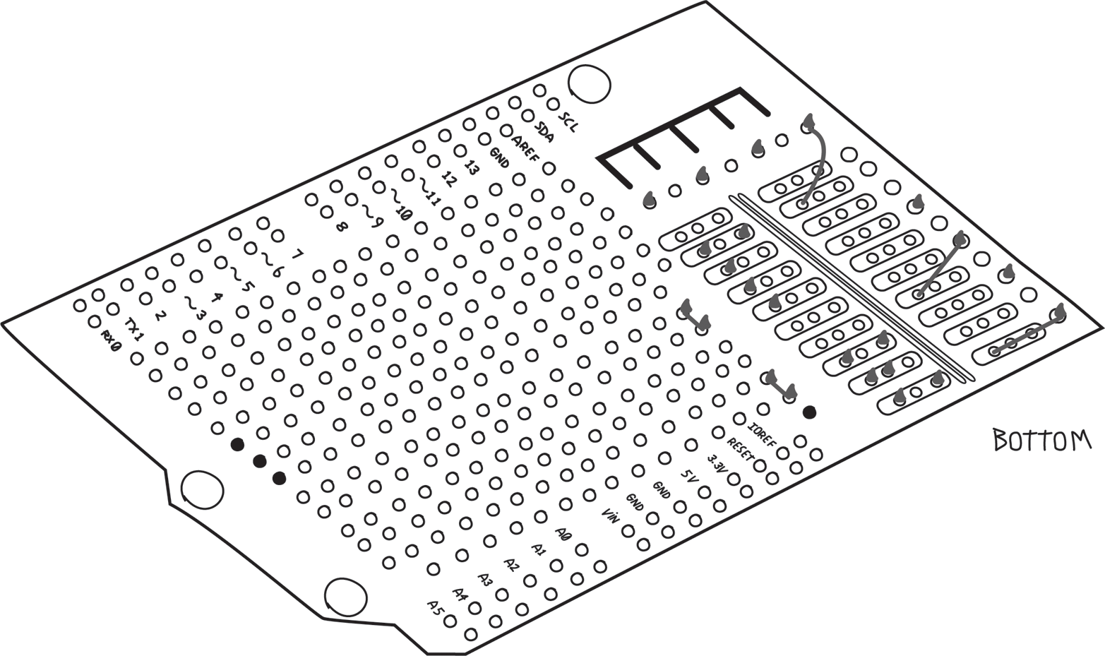
Note the black circle near IOREF. That’s a ground connection and must not be used unless you’re making a connection to ground.
This is a complicated section. Study it carefully and don’t solder anything until you are sure you understand what it’s doing and are convinced it’s going to the right place.
Now that all the components are on the shield, you have to wire up the remaining connections; use 22 AWG solid-core wire. Smaller would work as well but might be harder to work with. Use whatever works for you.
NOTE
Choose a consistent color scheme: use red wire for anything connecting to 5V and black wire for anything connecting to ground. You can make up your own colour coding for the others, but don’t use red or black for anything else. You might want to use orange for the water valve power supply positive connections, and green for the water valve power supply negative connections. Any wires that connect together should be the same colour, and any wires that do not connect together should be different colours.
The general principle is this: wires go on the top, and into holes that are next to the pin you need to connect to. On the bottom, you fold the wire over and solder to the appropriate pin, just as you did earlier with the component leads.
All the Arduino pins have their own holes, so you don’t need to fold the wire over. Just solder the wire in the appropriate hole.
Sometimes you simply can’t get close to the pin you need from the top. In these cases, it’s OK to put the wires on the bottom, but make sure to keep them as flat as possible.
Let’s start with the MOSFETs and their related circuitry. We’ve made all the connections we could with the leads. We need to connect the pin number 1 of all the relays to 5V. I’ve added red wires to make the 5V connection as shown in Figure 8-24 (remember the GND connection we’ll make at the end).
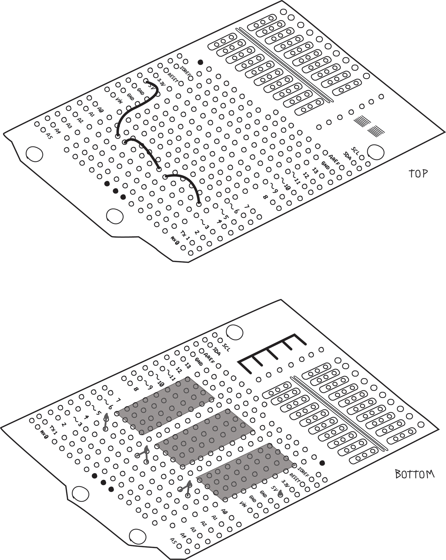
Next, connect all the positive screw terminals. This is all done on the bottom of the board, as shown in Figure 8-25. Make sure not to allow any leads or solder to touch those 5V and GND buses!
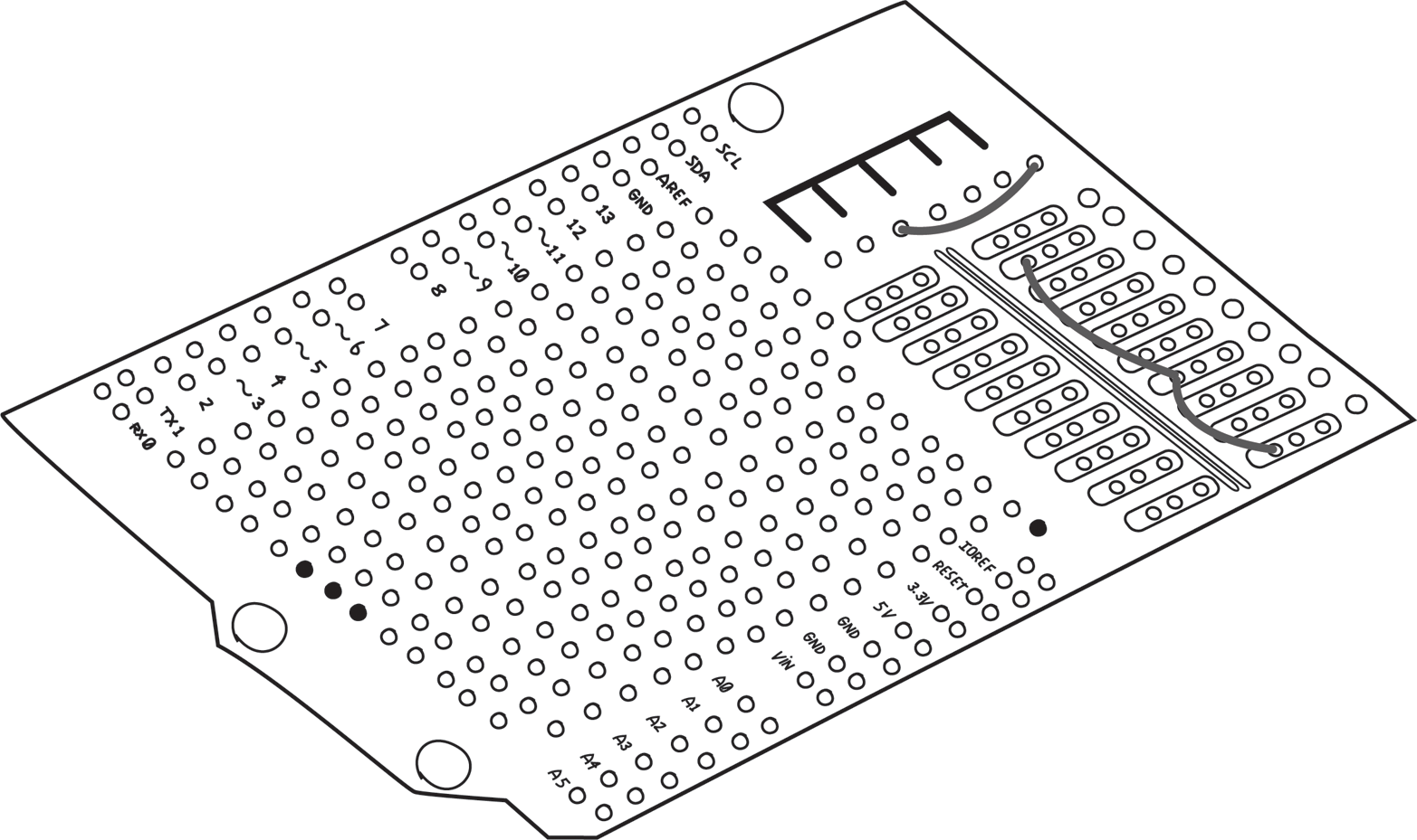
Connect the LED/resistor/diode chain to the negative screw terminal. Keep the middle hole clear, as we’ll use it in the next step to connect to the relays. In this case, I used two wires on the top and one on the bottom, as shown in Figure 8-26.
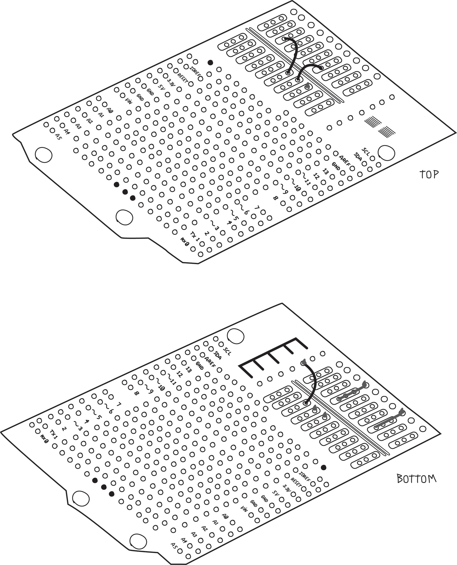
Now connect pin 8 of each relay to the appropriate negative screw terminal, as shown in Figure 8-27.
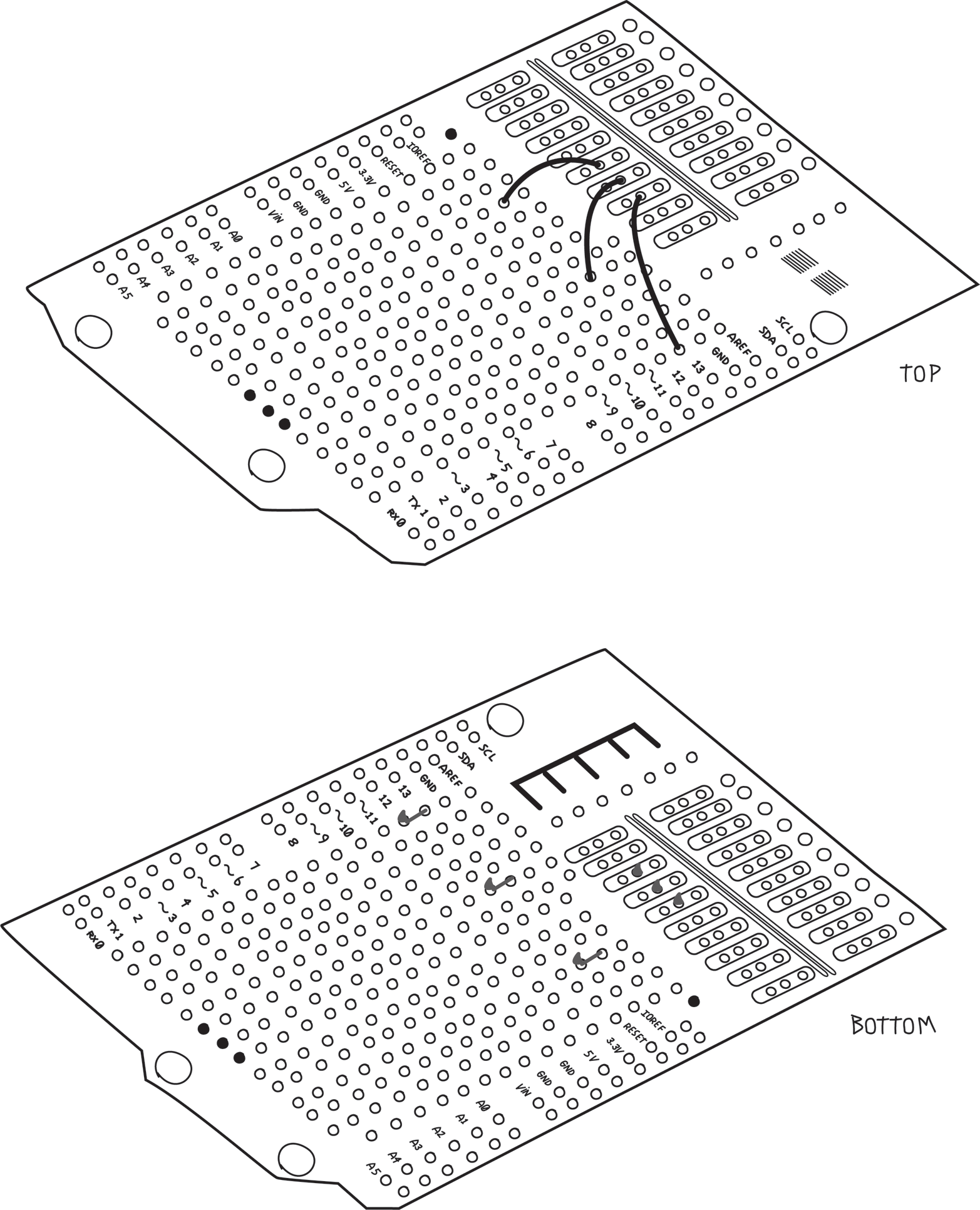
Pin 4 of all the relays connect to the negative screw terminal of the water valve power supply. This is done with two wires on the top and one on the bottom, as shown in Figure 8-28.
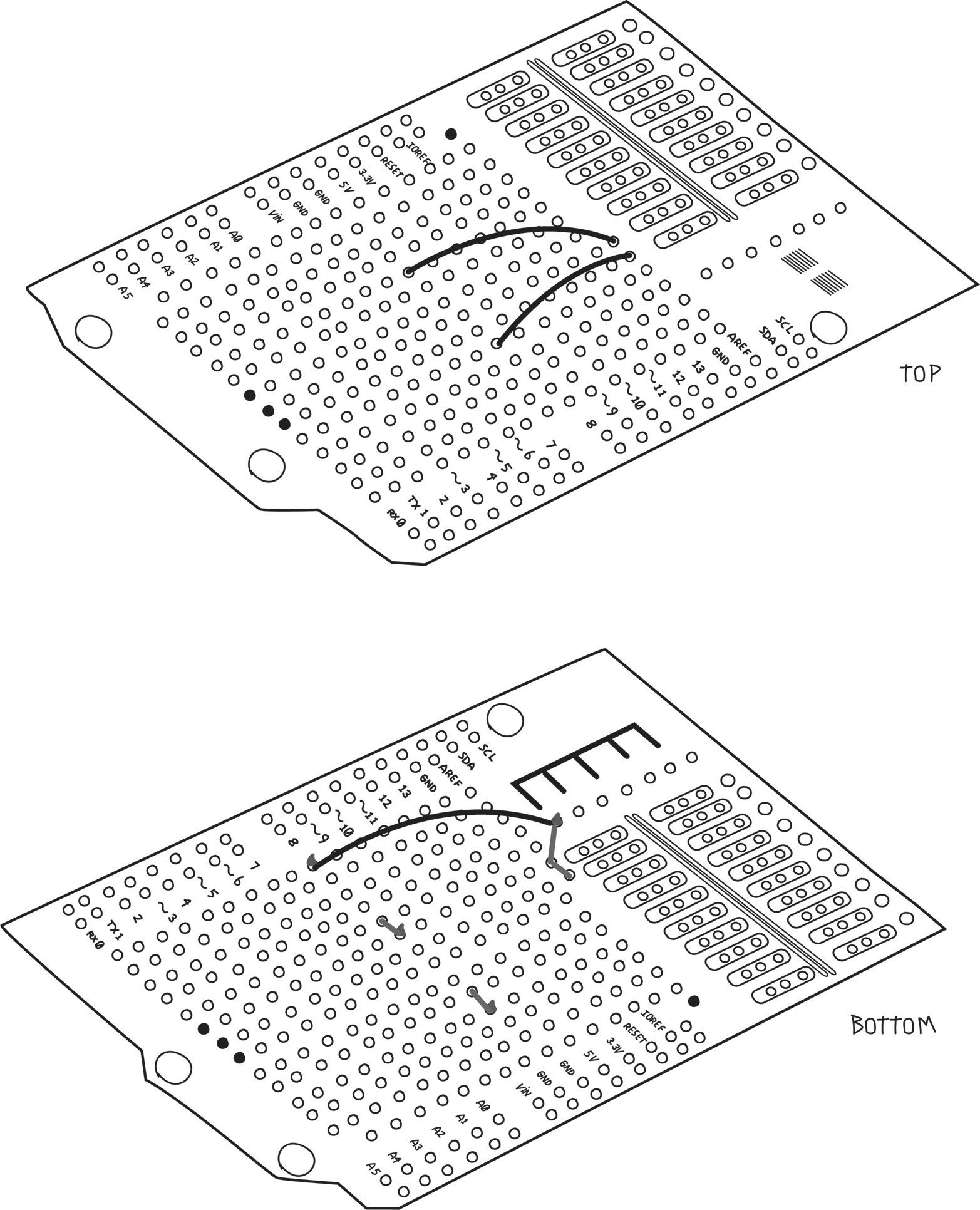
Next, connect the Arduino digital pins to the MOSFET gates, as shown in Figure 8-29. Remember the holes next to the Arduino pins are already connected to the Arduino pins so you don’t need to bend the wire and solder it directly to the pin.
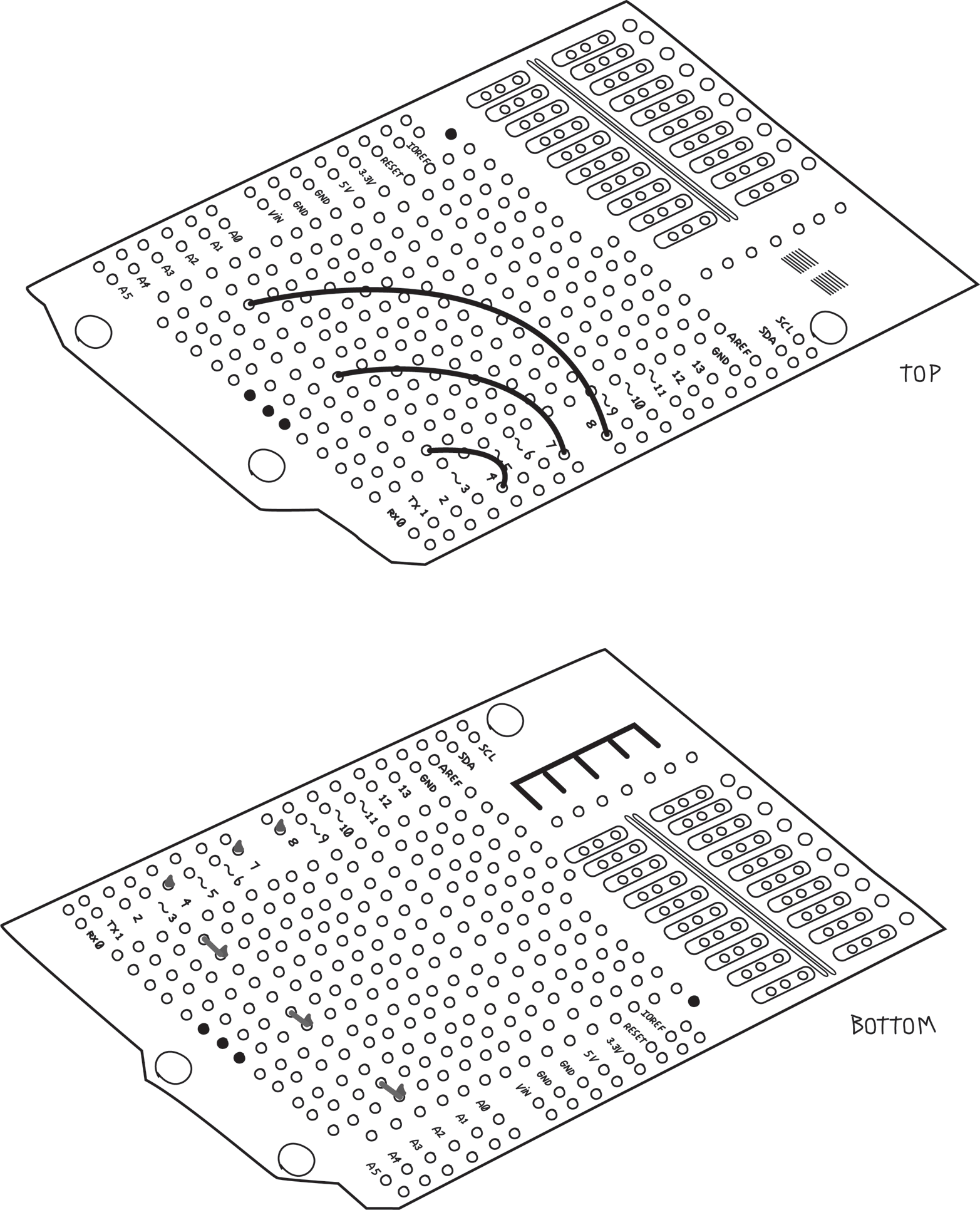
Finally, add the two sockets: one for the RTC and one for the DHT11, and connect them to the appropriate Arduino pins. Don’t forget the 10K ohm resistor that the DHT11 needs, as shown in Figure 8-30. I’ve also taken this opportunity to connect the ground bus we created earlier to the Arduino GND pin.
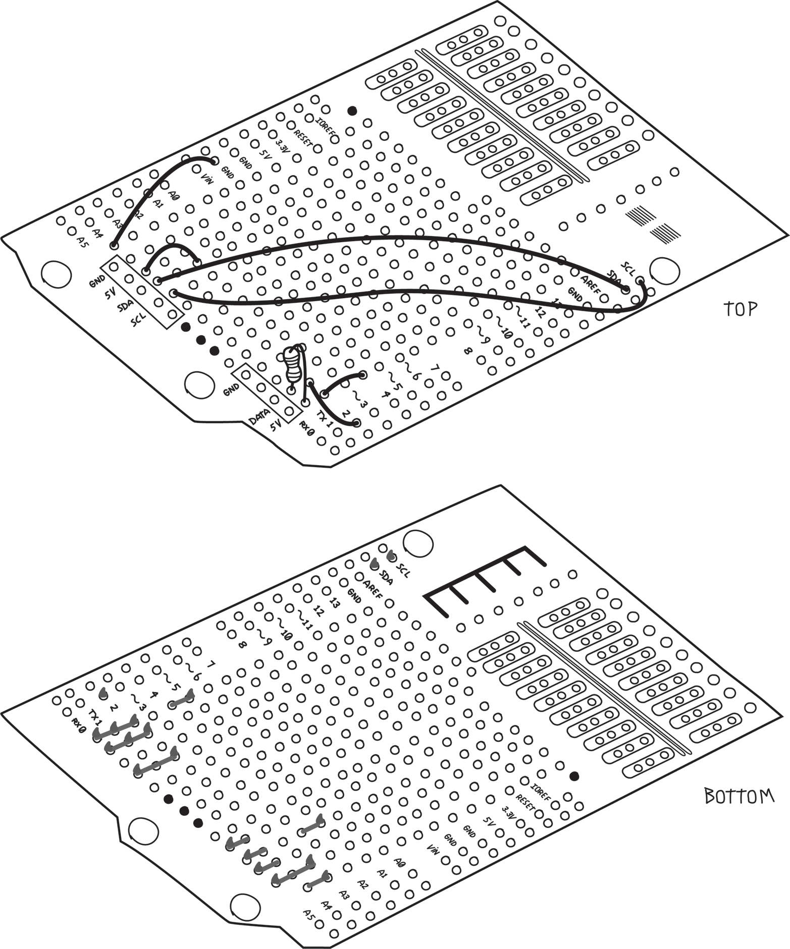
Document which pins do what on the sockets, so that you can plug in the RTC and the DHT11 properly (an ultrafine Sharpie is handy for this).
The last step is to solder in the male or pass-through headers that will fit into the Arduino pins. This should be done last because the headers get in the way of the work you are doing on the bottom of the shield. Although you don’t need all the pins, it’s wise to put them all in for mechanical strength and possible future enhancements.
Don’t forget that the male pins should point down; that is, towards the Arduino, as shown in Figure 8-34. Make sure the pins are straight so that they will fit into the sockets on your Arduino.
Leave a Reply