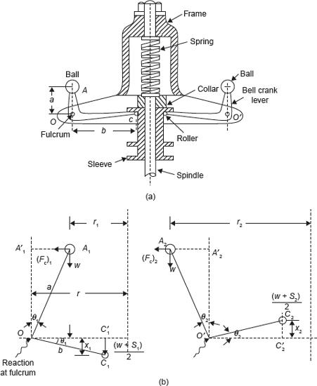
The Hartnell governor is shown in Figure 14.7(a). The two bell crank levers are used which can rotate about fulcrums O and O′. One end of both bell crank lever carries a ball and a roller at the other end of the arm. The rollers make contact with the sleeve. A helical spring is mounted on the spindle between frame and sleeve. With the rotation of the spindle, all these parts rotate.

Figure 14.7 (a) Hartnell Governor and (b) Force Analysis of Hartnell Governor
With the increase in speed, the radius of rotation of the balls increases and the rollers lift the sleeve against the spring force. With the decrease in speed, the sleeve moves downwards. The movement of the sleeve is transferred to the throttle of the engine through linkages.
Let
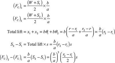
Considering the position of the ball at radius ‘r2’ as shown in Figure 14.7(b) and taking the moments of all the forces about O′.

If θ1 and θ2 are small. Weight w is small in comparision to W and spring force S, w tan θ1 and w tan θ2 can be neglected.

Example 14.5: A Hartnell governor having a central sleeve spring and two right angled bell crank levers moves between 280 and 320 rpm for a sleeve lift of 15 mm. The sleeve arms and the ball arms are 100 and 120 mm, respectively. The levers are pivoted at 120 mm from the governor axis and mass of each ball is 4 kg. The ball arms are parallel to the governor axis at the lowest equilibrium speed. Determine load on spring at lowest and highest speeds and stiffness of the spring.
Solution:
Let
S1 = Load on spring at lowest speed
S2 = Load on spring at highest speed
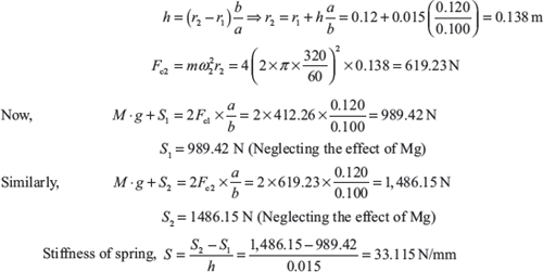
Since the ball arms are parallel to governor axis at the lowest speed, therefore, r = r1 = 120 mm

Let r2 is radius of rotation at N2 = 320 rpm.

Leave a Reply