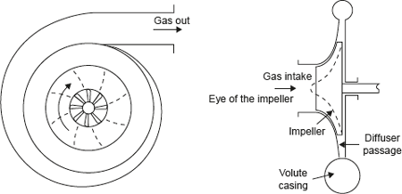
In these compressors the pressure rise takes place due to the continuous conversion of angular momentum imparted to the gas by a high-speed impeller into static pressure. Unlike reciprocating compressors, centrifugal compressors are steady flow devices hence they are subjected to less vibration and noise. Figure 10.9 shows the working principle of a centrifugal compressor. As shown in the Figure 10.9, low pressure enters the compressor through the eye of the impeller. The impeller consists of a number of blades, which form flow passages for gas.

Figure 10.9 Centrifugal Compressor
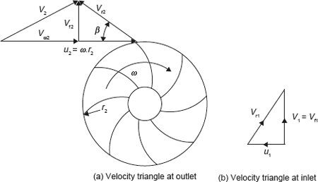
From the eye, the gas enters the flow passages formed by the impeller blades, which rotate at very high speed. As the gas flows through the blade passages towards the tip of the impeller, it gains momentum and its static pressure also increases. From the tip of the impeller, the gas flows into a stationary diffuser. In the diffuser, the gas is decelerated and as a result the dynamic pressure drop is converted into static pressure rise, thus increasing the static pressure further. The gas from the diffuser enters the volute casing where further conversion of velocity into static pressure takes place due to the divergent shape of the volute. Finally, the pressurized gas leaves the compressor from the volute casing. The velocity triangle for the centrifugal compressor is shown in Figure 10.10.

Figure 10.10 Velocity Diagram at the Outlet of the Impeller of a Centrifugal Compressor
Here,
- V = Absolute velocity of gas;
- u = Blade velocity;
- Vr = Relative velocity;
- Vω = Whirl component of absolute velocity; and
- Vf = Flow or normal component of absolute velocity.
Further, suffix 1 and 2 represent the conditions at inlet and outlet of the impeller.
For inlet velocity diagram, it has been assumed that gas enters the impeller eye in an axial direction, i.e., the whirl component of absolute velocity, Vω1 is zero. Flow component of absolute velocity, Vf1 = V1 (Figure 10.10b).
In general, we consider the flow of a gas through a rotor of any shape; the rate of change of angular momentum is given by (Vω2r2 − Vω1r1) m/skg.

It has been observed that for backward curved vanes (β < 90°), the tangential component of absolute velocity is much reduced and consequently for a given impeller speed, the impeller will have a low energy transfer. In case of forward curved vanes (β > 90°), the tangential component of absolute velocity is increased and consequently the energy transfer for forward curved vane is maximum. However, the absolute velocity at impeller outlet is also increased. High value of the absolute velocity is not desirable as its conversion into static pressure cannot be carried out efficiently in diffuser section. Normally, backward vanes with β between 20 and 25° are employed except in the case where high head is the major consideration.
Leave a Reply