In centrifugal pump, transformation of energy from mechanical to hydraulic form is done by rotating action of impeller, but in reciprocating pump this energy transformation is done by reciprocating action of piston. In reciprocating pump, the rotary motion of crank shaft is converted into reciprocating motion of pump by means of a connecting rod. Pressure on water is applied by reducing the volume by positive displacement method.
The main components of reciprocating pump are cylinder, piston or plunger, connecting rod, crank, suction pipe and delivery pipe as shown in Figure 9.19. Suction and delivery pipes are connected to the cylinder through one way valves. In a single acting reciprocating pump, piston moves towards right through 0° to 180° of crank and small vacuum is created inside the cylinder. Due to this vacuum, suction valve is pushed up and water enters into the cylinder. When piston moves towards right through 180° to 360° of crank rotation, suction valve is closed and delivery valve is open due to high pressure of water. Thus, water is forced into the delivery pipe and raised to a required height.
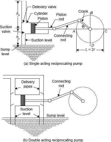
Figure 9.19 Working of Reciprocating Pump
Discharge through centrifugal pump,

Slip: It is difference between theoretical and actual discharge of reciprocating pump
Slip = Qtheoretical − Qactual
Variation in Acceleration Head in the Suction and Delivery Pipes Due to Acceleration of the Piston
Pressure head due to acceleration in suction and delivery pipes:

where A is area of piston and as and ad areas of suction and delivery pipes, respectively.
Thus, acceleration heads depend on the value of θ as shown in Figure 9.20.
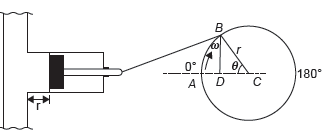
Figure 9.20 Velocity and Acceleration of Piston
Variation in Friction Head in Suction and Delivery Pipes Due to Variation in Velocity of Piston
Head loss due to friction is given by,

At θ = 90 head loss due to friction will be maximum and at θ = 0 head loss will be zero.
Case I: When acceleration heads and friction heads are zero (Figure 9.21).
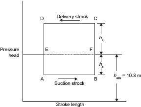
Figure 9.21 Ideal Indicator Diagram Without Acceleration and Friction Heads
Case II: When acceleration heads are not equal to zero (Figure 9.22).
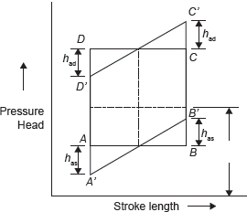
Figure 9.22 Indicator Diagram, When Acceleration Heads are not Equal to Zero, but Friction Heads are Zero
Case III: When acceleration heads and friction heads are not equal to zero (Figure 9.23).
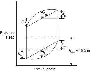
Figure 9.23 Indicator Diagram, when Acceleration Heads and Friction Heads are not Equal to Zero
Work done by pump for a single acting reciprocating pump

Work done by pump for a double acting reciprocating pump

Leave a Reply