Area of flow at inlet = ![]() , where D0 is outer diameter of runner and Db is hub diameter.
, where D0 is outer diameter of runner and Db is hub diameter.
Velocity triangle is similar to velocity triangle of Francis turbine. Only difference is that the velocity of flow at inlet and outlet in Kaplan turbine is same as shown in Figure 9.15.
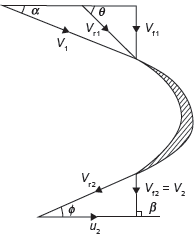
Figure 9.15 Velocity Triangle for Kaplan Turbine
Velocity of flow at inlet = Velocity of flow at outlet
i.e.,
Vf1 = Vf2
Peripheral velocity at inlet and outlet are equal,

Discharge through runner, Q = ![]()
Example 9.10: A Kaplan turbine is working under a head of 20 m. The hub diameter is 0.25 times the runner diameter. The rpm of the turbine is 500. Runner angle at outlet is 15° and flow ratio is 0.6. Calculate (i) diameter of runner, and (ii) discharge rate of water.
Solution:
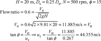
For Kaplan turbine, u1 = u2 = 44.3555m/s

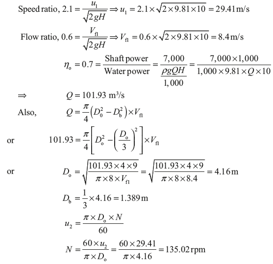
Example 9.11: A Kaplan turbine is designed to develop 7,000 kW shaft power. The head available is 10 m. Assuming speed ratio as 2.1, flow ratio as 0.6, overall efficiency as 70% and diameter of hub as one third of diameter of runner. Find the diameter of runner and its speed.
Solution:
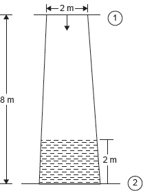
Example 9.12: A conical draft tube having inlet and outlet diameters 2 and 2.5 m discharges water at outlet with a velocity of 3 m/s. The total length of the draft tube is 8 m out of which 2 m of the length of the draft tubes immersed in water. If atmospheric pressure head is 10.3 m of water and loss of head due to friction in the draft tube is equal to 0.2 times of velocity head at outlet of the tube. Find (i) pressure head at inlet, and (ii) efficiency of draft tubes.
Solution:

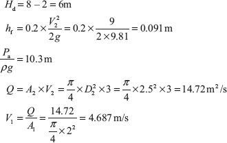
- Pressure head at inlet,

- Efficiency of draft tube, ηd =

Leave a Reply