A more “exact” deliverability relationship for stabilized gas flow was developed by Aronofsky and Jenkins (1954) from the solution of the differential equation for gas flow through porous media using the Forchheimer (rather than the Darcy) equation for flow. This solution is

where D is the non-Darcy coefficient and rd is the Aronofsky and Jenkins “effective” drainage radius, and is time dependent until rd = 0.472re. Otherwise,

where

The term Dq is often referred to as the turbulence skin effect, and for high rate wells it can be substantial. The non-Darcy coefficient, D, is frequently of the order of 10–3 and therefore a rate of 10 MMSCF/d would make the term Dq near the value of ln rd/rw (usually between 7 and 9). Smaller values of q would result in proportionately smaller values of Dq.
Frequently, Equation (4-47) is rearranged as

The first term on the right-hand side of Equation (4-50) is identical to the one developed earlier [Equation (4-42)] for Darcy flow. The second term accounts for non-Darcy effects. All multipliers of q and q2 can be considered as constant, and therefore Equation (4-50) may take the form

In field applications the constant a and b in Equation (4-51) can be calculated from a “four-point test” where (![]() )/q is graphed on Cartesian coordinates against q. The flowing bottomhole pressure, pwf, is calculated for four different stabilized flow rates. The intercept of the straight line is a, and the slope is b. From b and its definition [see Equation (4-50)], the non-Darcy coefficient, D, can be obtained.
)/q is graphed on Cartesian coordinates against q. The flowing bottomhole pressure, pwf, is calculated for four different stabilized flow rates. The intercept of the straight line is a, and the slope is b. From b and its definition [see Equation (4-50)], the non-Darcy coefficient, D, can be obtained.
Approximations for the non-Darcy coefficient have been given by a number of authors. In the absence of field measurements, an empirical relationship for a cased, perforated well is proposed by Jones (1987) as:

where γ is the gas gravity; ks is the near-wellbore permeability in md; h and hperf the net and perforated thickness, both in ft; and μ is the gas viscosity in cp, evaluated at the flowing bottomhole pressure.
Katz et al. (1959) have presented a more comprehensive expression for natural gas flow with turbulence:

where k equals the horizontal permeability, kH. β is the non-Darcy coefficient in the Forcheimer equation and can be calculated by using the Tek, Coats, and Katz (1962) correlation:

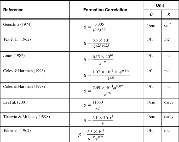
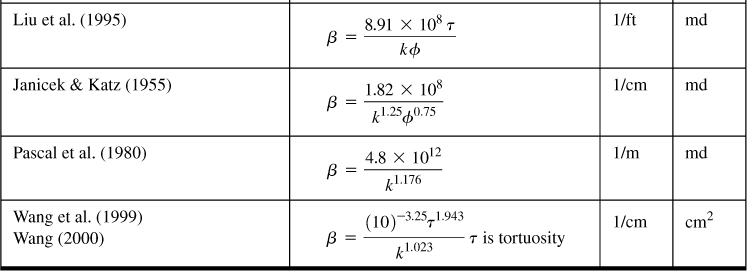
Equation (4-53) is for open-hole completions. Other correlations for non-Darcy flow coefficients for flow in the formation are listed in Table 4-5.
Table 4-5. Correlations for the non-Darcy Coefficient for Flow in the Formation


Example 4-7. Development of a Gas Well Deliverability Curve
Use the data in Appendix C and re = 1490 ft (A = 160 acres), ![]() = 0.022 cp,
= 0.022 cp, ![]() = 0.93, and ct = 1.5 × 10⁻⁴ psi–1. Develop a deliverability relationship, and graph the Darcy and non-Darcy components and the correct deliverability curve. Show the absolute open-flow (AOF) potential, that is, what the flow rate would be if pwf = 0. The skin effect is equal to 3, and the non-Darcy coefficient, D, is equal to 4.9 × 10⁻² (this is a very large coefficient).
= 0.93, and ct = 1.5 × 10⁻⁴ psi–1. Develop a deliverability relationship, and graph the Darcy and non-Darcy components and the correct deliverability curve. Show the absolute open-flow (AOF) potential, that is, what the flow rate would be if pwf = 0. The skin effect is equal to 3, and the non-Darcy coefficient, D, is equal to 4.9 × 10⁻² (this is a very large coefficient).
Solution
The first step is to calculate the time required for stabilized flow. From Equations (4-48) and (4-49),

which leads to

Therefore, the stabilized relationship implied by Equation (4-50) will be in effect after this time.
The coefficients a and b in Equation (4-51) can be calculated next:

and

The deliverability relationship for this well is then

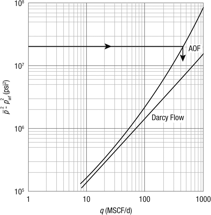
Figure 4-7 is a log–log graph of the Darcy flow result and the correct curve incorporating non-Darcy effects.

Figure 4-7. Deliverability relationship for the gas well in Example 4-7. Non-Darcy and Darcy effects.
The AOF potential for the correct curve (at pwf = 0 and therefore ![]() = 2.13 × 10⁷ psi2) is 460 MSCF/d, whereas this AOF, when taking into account only the Darcy flow contribution, would be 1420 MSCF/d.
= 2.13 × 10⁷ psi2) is 460 MSCF/d, whereas this AOF, when taking into account only the Darcy flow contribution, would be 1420 MSCF/d.
Example 4-8. Estimation of the Non-Darcy Coefficient
Calculate the non-Darcy coefficient for the well in Appendix C. Assume that ks is the same as the reservoir permeability, but that hperf = 39 ft (half the net thickness). Use a viscosity μ = 0.02 cp. What would happen if the near-wellbore permeability is reduced by damage to one-tenth of the reservoir permeability?
Solution
From Equation (4-52) and substitution of the variables in Appendix C,

If ks = 0.017 md, then D = 4.5 × 10⁻⁴ (MSCF/d)–1.
Leave a Reply